1 minute read
Lift Arm and ROPS/FOPS


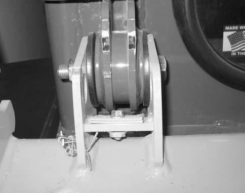
2.On both sides of the ROPS/FOPS: a.Install 2 rubber washers (B, Fig. 206) on the ROPS/FOPS mounts. b.Lower the ROPS/FOPS, guiding the mounts between brackets (C) on the frame.
Warning
Keep hands and feet clear when positioning ROPS/FOPS on the machine. Severe pinching/ crushing injury can occur.
c.Install screw (D), nut (E), and two flat washers (F).
Lift Arm and ROPS/FOPS
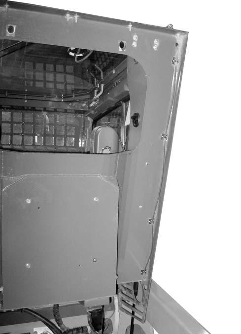
d.Lower ROPS/FOPS (A, Fig. 207) onto the frame, and reconfigure the lifting straps to raise the front of the ROPS/FOPS.
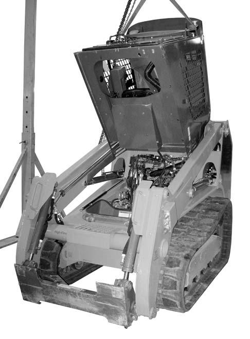
e.Lift the front of the ROPS/FOPS as shown, and support the ROPS/FOPS in the lifted position with the lifting straps.
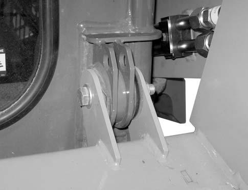
3.On both sides of the ROPS/FOPS, raise support strut (G, Fig. 208), and install pin (H) and spring clip (I).
Warning
Always secure the ROPS/FOPS in the tilted position with a suitable supporting device. Never allow anyone under the ROPS/FOPS if it is not securely supported.
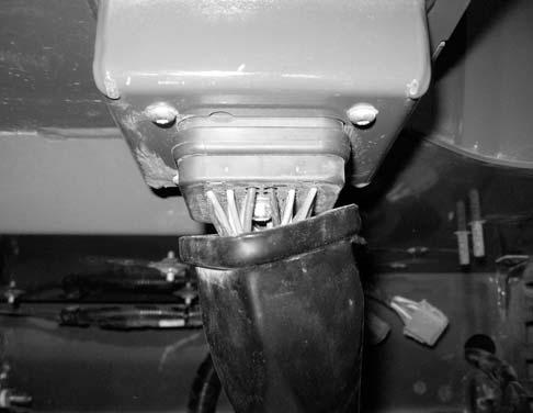
4.Connect wiring harness connector (J, Fig. 209) to the cab connector. Secure connector (J) using retaining screw (K). Position boot (L) over connector (J).
Lift Arm and ROPS/FOPS
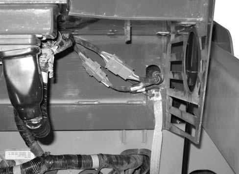
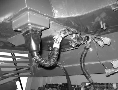
6.Connect wiring connectors (N and O, Fig. 210) to the chassis harness.
7.Connect ground strap (P) and ground wire (Q) to the ROPS/FOPS floor using nut (R). Tighten securely.
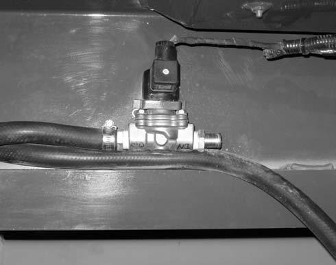
8.Connect wiring connector (S, Fig. 211) to heater control valve (T) solenoid.
Lift Arm and ROPS/FOPS
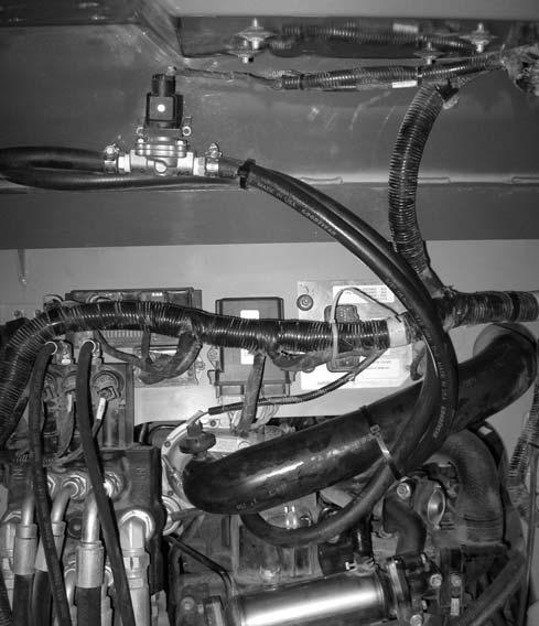
9.Route heater return hose (U, Fig. 212) into engine compartment.
12.Route windshield washer hose (Y, Fig. 213) along the bottom of the ROPS/FOPS, and secure hose (Y) using 6 cable ties (X).
10.Connect heater hose (V) to heater control valve (T). Secure hose (V) using hose clamp (W). Tighten securely.
11.Secure hoses (U and V), as shown, using cable ties (X).
13.Push windshield washer hose (Y) through hole/ grommet (Z) in the floor of the ROPS/FOPS.
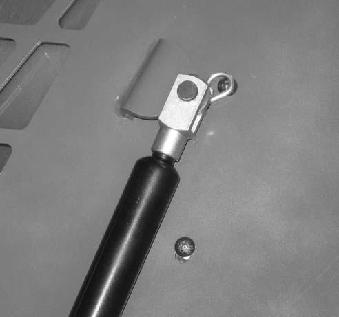
14.Postion ROPS/FOPS tilt prop bar (Y, Fig. 214) into the bracket on the bottom of the ROPS/ FOPS and replace hardware/components removed during ROPS/FOPS removal. Secure ROPS/FOPS prop bar (Y) with nut (X).
IMPORTANT: Replace the tilt prop bar components to match their positions prior to removal. Refer to Fig. 213.
15.Tilt the ROPS/FOPS down.
16.Model 1750RT (Serial Numbers 30870 and before), and Model 2100RT (Serial Numbers 40420 and before) a.Replace tilt stop plates (H, Fig. 215) in ROPS/FOPS tilt hinge bracket and secure with bolt (F).
Model 1750RT (Serial Numbers 30870 and Before) Model 2100RT (Serial Numbers 40420 and Before)


