1 minute read
Lift Arm and ROPS/FOPS


3.Shut off the engine. With the operator staying in the operator’s position a second person must support the raised lift arm using a suitable overhead crane/hoist. Once the lift arm is properly supported, the operator can exit the machine.
4.With the tilt cylinders fully extended:
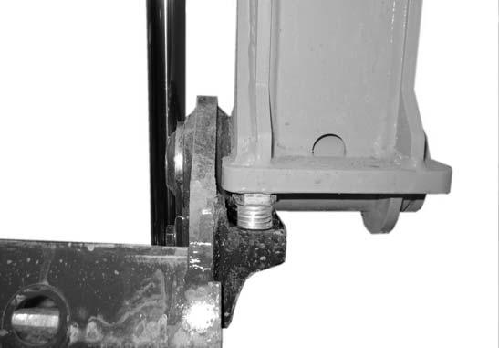
•If both tilt stop screws (A, Fig. 173) just touch lift arm stops (V), skip to step 15.
•If both tilt stop screws (A) DO NOT just touch lift arm stops (V), proceed to the next step in this procedure.
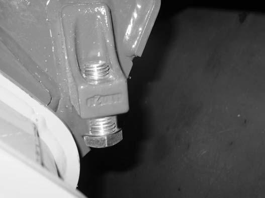
5.Start the machine and tilt/rotate the attachment hitch back far enough to install screws into brackets (T, Fig. 172) on both sides of the attachment hitch. Stop the machine.
6.Install 3/4” x 2” screws (C) into both brackets (T). Loosely tighten screws (C) by hand to allow for further adjustment.
7.Start the machine and tilt/rotate the attachment hitch forward until the tilt cylinders are fully extended. Stop the machine.
IMPORTANT: Two special tilt stop adjustment screws [Manitou part # 50302454] are required to perform the rest of this procedure.
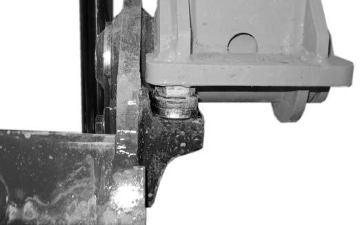
8.Adjust both screws (C, Fig. 173) so they just touch lift arm stops (V) when the tilt cylinders are fully extended.
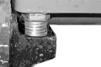
9.Measure and record the length of exposed threads (S, Fig. 174) on both screws (C).
IMPORTANT: Each screw/side may have a different dimension (S). Each should be measured and recorded separately.
Lift Arm and ROPS/FOPS
12.Install special tilt stop adjustment screws [Manitou part # 50302454] (E, Fig. 175) in place of screws (C, Fig. 174) removed in the previous step, with the washer combinations (D, Fig. 175) selected in the previous step.
IMPORTANT: Install washers so any thinner washers are sandwiched between thicker washers. Use as few of any thinner washers as possible.
10.Start the machine and tilt/rotate the attachment hitch back far enough to remove screws (C). Stop the machine.
11.Remove screws (C, Fig. 172). Select two combinations of 3/4” washers (D) to match measurements (S, Fig. 174) taken in the previous step.
IMPORTANT: Make sure each washer combination is correct for each side of the attachment hitch.
13.Tighten tilt stop adjustment screws (E) securely.

14.Start the machine and tilt/rotate the attachment hitch forward until the tilt cylinders are fully extended. Verify that the heads of tilt stop adjustment screws (E) just touch lift arm stops (V) when the tilt cylinders are fully extended.
15.Remove the overhead crane/hoist support from the lift arm and lower lift arm.


