41 minute read
Operation


Warning
Read and understand the entire operator’s manual. Follow warnings and instructions for operation and maintenance. Failure to follow instructions can result in injury or death.
Read and understand all safety decals before operating the machine. DO NOT operate the machine unless all factory-installed guards and shields are in place.
Be sure you are familiar with all safety devices and controls before operating the machine.
Know how to stop the machine before starting. Use only Manitou-approved accessories or referral attachments. Manitou Americas, Inc. cannot be responsible for safety if the machine is used with non-approved accessories or attachments.
Check for correct function after adjustments or maintenance.
Operational Checks
Pre-Start Checks
Complete these checks before starting the engine and using the machine. Repair any problems before using the machine.
Table 31: Pre-Start Checks
CheckRefer To: Fuel tank filled?
Engine oil level correct?
Hydraulic system oil level correct?
Engine coolant level correct?
“Adding Fuel” on page128
“Checking Engine Oil Level” on page120
“Checking Hydraulic Oil Level” on page131
“Checking Coolant Level” on page124
Table 31: Pre-Start Checks
CheckRefer To:
Windshield washer reservoir filled?
Grease fittings properly lubricated?
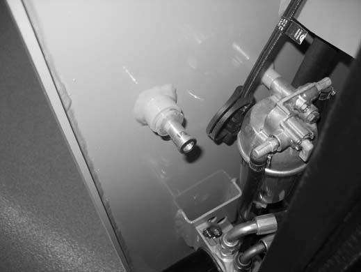
“Windshield Washer Reservoir” on page154
“General Lubrication” on page139
V-belt condition good/tension adjustment correct?
“Work Lights” on page70
“Checking and Adjusting Belt Tension” on page126 Track condition good? Lights, signals, indicators, warning lights, indicators and horn operating properly?
Windows, lights and steps clean? Attachment securely fastened to hitch?
Overall machine condition (including attachments) for bends, cracks, broken or missing parts, etc.
Engine cover securely closed and latched?
Rags, tools, debris and other loose objects removed? (check especially after maintenance)
Approved warning triangle, hazard warning light and first aid kit in the machine?
Seat position correctly adjusted?
Armrests/joystick consoles correctly adjusted?
“Connecting Attachments” on page105
“Engine Access” on page119
If required by local regulations
“Seat and Armrest/ Joystick Console Adjustment” on page76
“Armrest/Joystick Console Adjustment” on page65
Seat belt fastened?“Seat Belt” on page77
Parking brake applied? “Parking Brake” on page77
Checks During Operation
Complete these checks after starting the engine and during operation:
Table 32: Checks During Operation
CheckRefer To:
Always after Starting the Engine / During Operation Engine oil pressure and charge indicator lights not on?
Park brake operating properly?
Coolant temperature within specification?
Track drive/steering operating properly?
Engine exhaust excessively smoky?
Anyone hazardously close to the machine?
Visually check if automatic track tensioning is operating correctly.
Hydraulic functions sluggish or too sensitive?
Travel drive operation sluggish or too fast?
When Driving on Public Roads
“Multi-Function Display” on page50
“Travel Drive Operation” on page90
“Multi-Function Display” on page50
“Travel Drive Operation” on page90
Parking Checks
Complete these checks when parking the machine:
Table 33: Parking Checks
CheckRefer To:
Always when Parking
Mandatory Safety Shutdown Procedure performed? “Mandatory Safety Shutdown Procedure” on page22
Attachments lowered to the ground?
Parking brake applied?
Machine cab locked (especially if the machine will not be supervised).
When Parking on Public Sites
Machine adequately secure/cab locked?
Adjust control function sensitivity according to “Joystick Control Sensitivity” on page60
If equipped, adjust travel speed limit according to “Travel Speed Limit (Option)” on page67
Attachments in transport position? “Attachment Transport Position” on page96
Machine work hydraulics lockedout?
“Parking Brake/Work Hydraulics Lock-out” on page63
“Parking Brake/Work Hydraulics Lock-out” on page63
Before Operation
Cab Entry and Exit
Warning
Always perform the “Mandatory Safety Shutdown Procedure” on page22 before exiting the machine.
Use only step (S, Fig 42) and handles (R) on the machine when entering/exiting the cab. Keep the steps and the handles clean to ensure a secure hold at all times. Never use the control joysticks as hand holds. Remove dirt (oil, grease, earth, snow and ice) from handles (R), steps (S) and your shoes before entering the cab.
Always face the machine when entering/exiting.
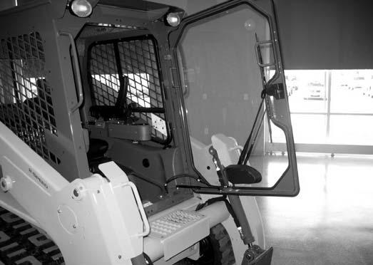
When entering/exiting the cab, open the door fully to the locked position and check that it does not move (machines equipped with cab door).
Do not jump on or off the machine. Never climb onto or exit a moving machine.
Opening/Closing the Cab Door (Option)
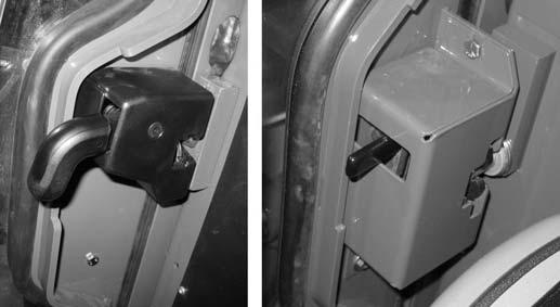
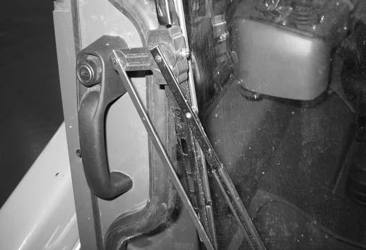
Operate the door latch outside the cab using button (Z, Fig 43) on the exterior door handle.
Lock/unlock the door using the ignition key in the key slot in button (Z).
Operate the door latch inside the cab using lever (Y, Fig 44) located along the interior door frame.
Cab Door Removal
If the cab door is removed, the jumper wire inside the left door pillar must be repositioned or the machine will not operate.

1.Unplug door switch wire connector (B, Fig. 45) from “Door Switch” wire connector (D).
2.Transfer jumper (J) from “Wiper Interlock” wire connector (E), to “Door Switch” wire connector (D).
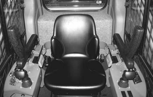
Seat and Armrest/Joystick Console Adjustment
Adjust the operator’s seat according to “Operator’s Seat” on page64.
Adjust the armrest/joystick position according to “Armrest/Joystick Console Adjustment” on page65.
Warning
Never adjust the seat and/or the armrest/ joystick consoles when the machine is in operation. Adjust the seat and/or the armrest/ joystick consoles only when the machine is stopped and the parking brake is applied.
All controls must be within easy reach. The operator must be able to move the throttle pedal and the control joysticks through the complete range of motion.
After adjustments, make sure levers for the seat and/or the armrest/joystick console adjustments are fully engaged before using the machine.
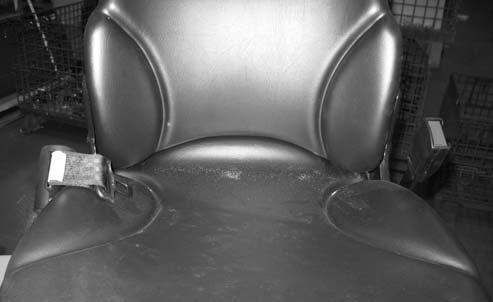
Seat Belt
Fasten the seat belt around your hips and waist and insert tongue (A, Fig 46) into clasp (B) until it clicks securely in place. Slack in the seat belt should automatically retract into seat belt spool (K).
Warning
Never operate the machine without the seat belt fastened. Repair or replace any damaged seat belt and lock parts before operation.
NOTE: Raising the safety bars/arm rests, leaving the operator’s seat or opening the cab door also locks out work hydraulic functions, with the exception of standard auxiliary hydraulics continuous flow.
Warning
If the seat belt spool does not retract the slack in the seat belt, have it serviced immediately. Do not operate the machine if the seat belt is not fastened and working properly.
NOTE: Unfasten the seatbelt by pressing button (C).
Parking Brake
The parking is automatically applied whenever either of the safety bars/arm rests are in the raised position (B, Fig 47), the operator leaves the seat or the cab front door is opened.
Before starting the engine, sit in the operator’s seat and lower the safety bars/arm rests. On machines equipped with a cab, close the door.
IMPORTANT: The engine cannot be started if the safety bars/arm rests are in the raised position, the cab door is open or the operator in not in the seat.
Disengage Parking Brake
1.Sit in the operator’s seat and fasten the seat belt.
2.Close the cab door, if equipped.
3.Lower the safety bars/arm rests.
4.Start the engine.
NOTE: If the engine does not start due to failure to perform any of steps 1-3, the error code “0” is displayed on the multi-function display.
5.Press and hold the top of the parking brake switch (C, Fig 48) for several seconds until the indicator lights in the switch and on the multifunction display go out.
Starting the Engine
NOTE: The machine cannot be push- or towstarted. Attempting to push/tow start the machine may damage the drive systems of both the machine and the push/tow vehicle.
1.Complete the “Pre-Start Checks” on page73.
2.Sit in the operator’s seat and adjust the seat as required.
Caution
All controls must be within easy reach. The operator must be able to move the throttle pedal and the control joysticks through the complete range of motion.
3.Fasten the seat belt.
Warning
Always fasten the seat belt before operating the machine. Repair or replace any damaged seat belt and lock parts before operation.
4.Close the cab door, if equipped.
5.Lower both arm rests/safety bars.
IMPORTANT: The arm rests/safety bars must be lowered before the engine can be started. An engine error code (0) will display on the multi-function display if the ignition is switched to the start position when the arm rests/safety bars are in the raised position, the operator’s seat is not occupied or the cab door is not closed.
6.Insert the ignition key into the ignition switch (T, Fig 49) and turn the key clockwise to the first detent. Wait for the multi-purpose display to initialize completely. Indicators on the multifunction display should light up; a beeping tone will sound for a few moments as a reminder to fasten the seat belt. The battery voltage and preheat indicators might stay lit for 3-30 seconds.
NOTE: The pre-heat indicator may stay on for longer periods in colder ambient temperatures.
Cold-Starting
If operating in temperatures below 32°F (0°C), the following are recommended:
•Replace the engine oil with the proper viscosity oil according to the engine operator’s manual.
•Make sure the battery is fully charged.
•Install an optional block heater on the engine. A block heater is recommended for starting in temperatures below 20°F (-7°C). Contact your dealer for engine heater options.
NOTE: In ambient temperatures below -10° C (14° F), an engine block heater is recommended to reduce starter load and aid engine warm up. Starting the machine at these temperatures without a block heater will result in multiple glow/crank cycles or possible extended cranking time approaching 20 seconds.
After Starting
Check that charge (F, Fig 49) indicator goes out after the engine starts.
NOTE: When the key is turned clockwise to the first detent, seat belt indicator (H) activates and a tone sounds for 5 seconds as a reminder to fasten the seat belt.
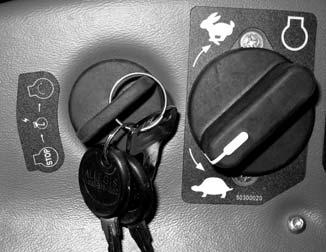
7.When the pre-heat indicator light (F) goes out, Turn the ignition key clockwise until the starter activates. Release the key when the engine starts.
8.If the engine does not start after 15 seconds, turn the ignition key all the way counter-clockwise, wait 1 minute and repeat steps 6-8. If the engine does not start after several attempts, see “Engine Troubleshooting” on page313.
9.Disengage parking brake according to “Disengage Parking Brake” on page78.
IMPORTANT: The lift arm and drive hydraulics are inactivated if the parking brake is engaged.
IMPORTANT: If the charge and/or the engine oil pressure indicators do not go out when the engine is running, shut down the engine immediately and correct the problem. Damage to the engine may result if engine is run and the problem is not corrected.
IMPORTANT: Do not run a cold engine at full throttle when starting. Stressing a cold engine can damage the engine. Perform the following warm up procedure before using the machine after starting.
Warm Up
Warning
Operating the work hydraulics before the hydraulics are warmed up is dangerous, because response will be slow and the machine might move in unexpected ways. Additionally, operating the machine before proper warm-up can also damage the machine. Be sure to sufficiently warm up the machine before starting work.
IMPORTANT: Do not operate the control joysticks suddenly until the hydraulic oil has reached operating temperature.
1.After starting, allow the engine to run at low idle for a minimum of 5 minutes with no load (no drive, lift, tilt or auxiliary hydraulic functions).
2.Run the engine at 1800 rpm with no load for 5 minutes.
3.Raise the lift arm so the attachment is off the ground.
4.Extend and retract each of the cylinders several times with no load.
5.Travel slowly forward and backward several times.
6.Additionally, in cold weather, tilt the attachment all the way forward and keep it there for 20-25 seconds. Repeat this step until the attachment tilt speed is normal.
NOTE: Engine speed may be limited during a cold start and/or during a travel drive error condition. See “Travel Drive Error Condition Operation (Limp Mode)” on page94.
Run-In Period
The performance and service life of the machine is heavily dependent on using the machine carefully during its first 100 operating hours.
•Do not operate machine at the maximum rated operating capacity.
•Do not run the engine at a high speed for extended periods of time.
•Increase the load gradually while varying the engine speed.
•Follow the maintenance schedule. See “Maintenance Schedule” on page116.
Stopping the Engine
Perform the “Mandatory Safety Shutdown Procedure” on page22.
IMPORTANT: Do not stop the engine at full throttle. Damage to the engine can result. Allow the engine to idle for approximately 2 minutes before shutting it off.
Engine Stalling WARNING
If the engine should stall for any reason during operation, always turn the ignition key all the way counter-clockwise to the “OFF” position before re-starting the engine according to “Starting the Engine” on page78.
Diesel Particulate Filter (DPF) Regeneration Procedures
Models 1750RT (Serial Numbers 131001 and Up) and 2100RT (Serial Numbers 241001 and Up)
The Diesel Particulate Filter (DPF) treats exhaust emissions in compliance with Tier 4 emission standards. The DPF filter relies on high exhaust temperatures. Periodic DPF maintenance (regeneration) is required, dependent upon machine operation load / temperature.
NOTE: Machines operated primarily at high loads and operating temperatures require less frequent DPF maintenance. Extended periods of engine idling rapidly increases DPF soot levels, requiring more frequent regeneration operations.
There are 3 modes of DPF regeneration:
• Passive / Assist Regeneration: Occurs automatically without operator input. Passive/assist regeneration does not effect machine operation.
• Reset Regeneration: Occurs automatically, but can be inhibited by the operator. Increases exhaust gas temperatures. Reset regeneration occurs approximately every 100 hours of operation. See “Reset Regeneration” on page82.
NOTE: Reset regeneration effectiveness is improved if the machine is operated at mid- to high-throttle settings while this mode is in progress.
• Stationary Regeneration: Requires operator action to initiate and takes approximately 25-30 minutes to complete. See “Stationary Regeneration” on page82.
IMPORTANT: The machine cannot be operated and must be parked in a well-ventilated area away from flammable materials when stationary regeneration is in progress.
Reset Regeneration
Reset regeneration occurs automatically (unless inhibited) approximately every 100 hours of operation.
NOTE: Reset regeneration effectiveness is improved if the machine is operated at mid- to highthrottle settings while regeneration is in progress. During reset regeneration, exhaust gas temperature warning icon (R, Fig. 50) is displayed at the right edge of all status screens.
195° F
NOTE: Reset regeneration can be prevented from occurring. See “Regeneration Inhibit” on page85.
When DPF regeneration is inhibited, DPF regeneration icon (J, Fig 51) is displayed at the bottom of all status screens.
If reset regeneration attempts to start but DPF regeneration is inhibited, a flashing DPF regeneration request icon (L) is displayed.
Stationary Regeneration
Stationary regeneration may be periodically required to reduce DPF soot build-up. The frequency of stationary regeneration is dependent upon machine operation and engine load.
The machine cannot be used during stationary regeneration and cannot be moved without interrupting the stationary regeneration process. When stationary regeneration needs to be performed, the DPF Stationary Regeneration Request Screen (Fig. 52) displays.
Caution
Permanently inhibiting regeneration is not recommended, as this will eventually cause significant reduction in engine power and will force premature DPF soot filter replacement.
NOTE: The stationary regeneration request screen can be temporarily dismissed by pressing and releasing the interface button. The stationary regeneration request screen will return 1 minute after being dismissed, for as long as the request remains active.
IMPORTANT: Perform stationary regeneration as soon as possible when the stationary regeneration request screen displays. Postponing stationary regeneration for extended periods will cause significant reduction in engine power and will force premature DPF filter core replacement.
To proceed with stationary regeneration:
1.Park the machine in a safe, well-ventilated location away from flammable materials.
2.The following conditions need to be met before stationary regeneration continues: a.Apply the parking brake using the parking brake switch or by lifting the safety bars/arm rests. A checkmark (M, Fig. 53) is displayed next to the parking brake icon in the middle of the stationary regeneration request screen. b.When engine coolant has reached operating temperature (above 140° F / 60° C), a checkmark (O) is displayed next to the coolant temperature icon. c.Place throttle controls to the lowest speed setting. A checkmark (P) is displayed next to the slow engine speed icon when the engine is running at low idle.
5.When stationary regeneration completes, the display returns to the coolant temperature status screen (Fig 55).
NOTE: Stationary regeneration can be interrupted at any time by releasing the parking brake, advancing the throttle, or stopping the engine. Stationary regeneration must start again from the beginning if it is interrupted.
3.When all three checkmarks (M, O & P) are displayed on the stationary regeneration request screen, press and hold the interface button on the multi-function display until the DPF Stationary Regeneration In Progress screen (Fig 54) is displayed.
4.Stationary regeneration progress is displayed in the center (X, Fig 54) of the DPF Stationary Regeneration In Progress Screen.
NOTE: Stationary regeneration takes approximately 25-30 minutes. When stationary regeneration completes, the display returns to the home status screen.
Caution
It is not necessary to stay in the machine during stationary regeneration. Keep the machine under observation while regeneration is in progress in case of malfunction. Keep bystanders away from the machine while regeneration is in progress.
Forcing Stationary Regeneration
To perform stationary regeneration on-demand:
1.Hold down the interface button (Z, Fig 57) on the multi-function display until the configuration selection screen displays.
2.Press and release the interface button until the selection caret points to the selection (Y, Fig 57). Press and hold the interface button until the DPF Regeneration Screen (Fig 58) displays.
5.Park the machine in a safe, well-ventilated location away from flammable materials.
6.The following conditions need to be met before stationary regeneration can be initiated: a.Apply the parking brake using the parking brake switch or by lifting the safety bars/arm rests. A checkmark (M, Fig. 60) is displayed next to the parking brake icon in the middle of the forced regeneration screen. b.When engine coolant has reached operating temperature (above 140° F / 60° C), a checkmark (O) is displayed next to the coolant temperature icon. c.Place throttle controls to the slow speed position. A checkmark (P) is displayed next to the slow engine speed icon when the engine is running at low idle.
3.Press and release the interface button to move box (H, Fig 58) around regeneration symbol (F), as shown in Fig.58.
NOTE: Regeneration symbol (F) will display only if it has been greater than 50 hours since the last reset or stationary regeneration. The icon will also only display if the machine is at operating temperature (60°C [140° F]).
4.With box (F) around the regeneration symbol, press and hold the interface button until the DPF Forced Regeneration screen (Fig 59) displays.
7.When all three checkmarks (M, O & P) are displayed on the forced regeneration screen, press and hold the interface button (Z, Fig 63) on the multi-function display, until countdown (W, Fig. 60) reaches “0” and stationary regeneration begins.
NOTE: The DPF Stationary Regeneration Progress Screen (Fig 61) displays with checkmark (Z) confirming that that stationary regeneration has started.
8.Stationary regeneration progress is displayed in the center (X, Fig 61) of the DPF Stationary Regeneration In Progress Screen. Engine speed automatically advances as required for the stationary regeneration process.
Regeneration Inhibit
NOTE: DPF regeneration inhibit prevents reset regeneration from occurring. Reset regeneration can be prevented from occurring using the multi-function display DPF regeneration configuration screen:
1.Hold down the interface button (Z, Fig 63) on the multi-function display until the DPF Regeneration configuration selection screen (Fig 64) displays.
2.Press and release the interface button until the selection caret points to the selection (Y, Fig 64). Press and hold the interface button until the DPF Regeneration Configuration (Fig 65) screen displays.
9.When stationary regeneration is complete, the display returns to the coolant temperature status screen (Fig 62).
3.Press and release the interface button to move box (H, Fig 65) around the regeneration inhibit symbol, as shown Fig.65.
NOTE: “EXIT” selection (G) returns the display to the coolant temperature status screen without changing DPF regeneration settings.
4.With box (H) around the regeneration inhibit symbol, press and hold the interface button until the regeneration inhibit symbol blinks.
5.Press and release the interface button to move box (H) around the “EXIT” selection (G). Press and hold the interface button until the configuration selection screen displays.
NOTE: When DPF regeneration is inhibited, DPF regeneration icon (J, Fig 66) is displayed at the bottom of all status screens.
If reset regeneration attempts to start but DPF regeneration is inhibited, a flashing DPF regeneration request icon (L) is displayed.
Caution
Permanently inhibiting regeneration is not recommended, as this will eventually cause significant reduction in engine power and will force premature DPF filter core replacement.
Cancelling Regeneration Inhibit
1.Hold down the interface button (Z, Fig 67) on the multi-function display until the DPF Regeneration configuration selection screen (Fig 68) displays.
2.Press and release the interface button until the selection caret points to the selection (Y, Fig 68). Press and hold the interface button until the DPF Regeneration Configuration (Fig 65) screen displays.
3.Cancel regeneration inhibit using one of the following two methods:
Method A:
A-1.Press and release the interface button to move box (H, Fig 69) around the regeneration inhibit symbol, as shown Fig.69.
A-2.With box (H) around the regeneration inhibit symbol, press and hold the interface button until the regeneration inhibit symbol stops blinking.
NOTE: Pressing and holding the interface button with box (H) around the regeneration inhibit symbol will toggle regeneration inhibit on and off: Regeneration inhibit is ON if the symbol IS blinking; regeneration inhibit is CANCELED if the symbol IS NOT blinking.
Method B:
B-1.Press and release the interface button to move box (H, Fig 70) around the force regeneration symbol, as shown Fig.70.
DPF Service
DPF soot filter replacement is required when the DPF Service screen (Fig 71) displays.
B-2.With box (H) around the symbol, press and hold the interface button until the DPF Forced Regeneration Screen (Fig. 59, page84) displays. Forced regeneration can be initiated, or “EXIT” can be selected to return to the configuration selection screen.
NOTE: “EXIT” selection (G, Figs. 69 and 70) returns the display to the the configuration selection screen without changing DPF regeneration settings.
IMPORTANT: DPF soot filter replacement requires the Yanmar SA-D (SMARTASSIST-Direct) tool.
Refer to the Yanmar 4TNV98C/CT engine service manual for DPF service information.
After Operation WARNING
Park the machine on firm, level ground. Raise the arm rests/safety bars to apply the parking brake and lock out the hydraulic controls.
Warning
Always apply the lift arm support if leaving the machine with the lift arm in the raised position See “Lift Arm Support” on page102.
If you must park on a slope or an incline, park across the slope and block the machine to prevent movement.
Warning
If parking on a street, use barriers, caution signs, lights, etc. to increase the visibility of the machine and prevent collisions. This is especially important at night, during bad weather and in high-traffic areas.
After performing the “Mandatory Safety Shutdown Procedure” on page22, perform the following tasks and checks:
•Check for coolant, fuel and/or oil leaks. Inspect all hoses, working components, covers and chassis for damage or advanced wear. Repair or replace damaged, leaking, worn or otherwise compromised components before starting the machine again.
•Fill the fuel tank. See “Fluids/Lubricants Types and Capacities” on page37.
•Remove any dirt and/or debris from the engine compartment.
•Remove any mud from the chassis. Clean any dirt or water from the cylinder rod surfaces to prevent corrosion and protect the cylinder seals.
•If parking the machine for an extended period, lock the cab door, the storage compartment, the battery and hydraulic filler compartments and the engine compartment. Take the keys with you.
Jump-Starting WARNING
Two people are required for safe jump-starting. An additional person is required to remove the jumper cables with the operator remaining in the operator's seat once the engine is running.
Warning
Do not jump-start a frozen battery, or it may explode. A discharged battery can freeze at 14°F (10°C).
IMPORTANT: The external power source must deliver 12 volts. Supply voltages higher than 12V can damage the electrical systems of both machines. Only use authorized jumper cables that are in good condition.
The booster battery must have a nominal voltage of 12-volts. The capacity (Ah, or Amp-hour rating) of the current-supplying battery must be approximately equal to that of the discharged battery. Factoryinstalled batteries are approximately 70 Ah capacity.
Caution
To reduce the risk of a short circuit, keep metal parts on your clothing and metal jewelry away from the positive (+) pole of the battery.
1.Turn the ignition switches of both machines to OFF. Be sure the machines are not touching each other. If the machine with the booster battery has a drive transmission, place the transmission into neutral and apply the parking brake.
2.Using the accessory key (supplied with the ignition key), unlock (H, Fig 72) and open the battery compartment located at the rear left corner of the machine. Open the battery compartment cover and lock the cover open using pin (D).
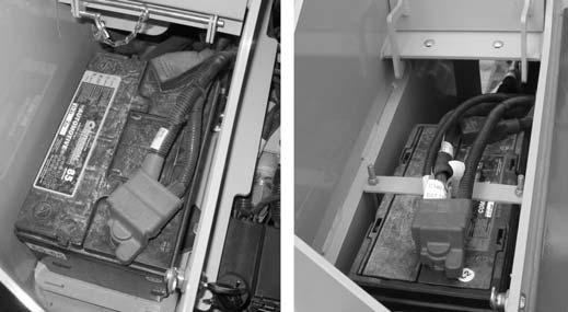
3.Check that battery jumper cables have a sufficient diameter. Route the jumper cables so that they cannot catch on any moving objects or components.
4.Connect the positive jumper cable to the positive (+) terminal (S, Fig 73) on the discharged battery.
Caution
Always lock the battery compartment cover open using pin (D). Severe injuries can result if the battery compartment cover falls on hands and/or fingers.
5.Connect the free end of the positive jumper cable to the positive (+) terminal (P) on the booster battery
6.Connect the negative jumper cable to the negative (-) terminal (N) on the booster battery.
7.Open the rear door of the engine compartment (“Engine Access” on page 119) and connect the free end of the negative jumper cable to the rear door catch (M, Fig 74) in the engine compartment.
Warning
Do not connect the other end of the jump lead to the negative terminal of the dead battery. Gas emerging from the battery may ignite if sparks are formed.
8.Start the machine with the discharged battery. See “Starting the Engine” on page78. If the engine does not start immediately, stop cranking after 10 seconds and repeat starting procedure after approximately 30 seconds.
After the Engine Starts:
1.With the operator remaining in the operator’s seat, the jumper cables are disconnected by a second person in reverse order of steps 4 – 6 to avoid sparking near the battery.
2.Close the rear door and the engine cover according to “Closing Engine Covers” on page119.
3.Allow the machine to run for at least 30 minutes to re-charge the battery.
Travel Drive Operation
Warning
Never allow anyone to enter inside the turning radius and the machine path.
Signal your intention to move by sounding the horn.
Traveling should be performed with the attachment in transport position. See “Attachment Transport Position” on page96.
Avoid sudden stops, starts or turns.
Do not raise the arm rests/safety bars while traveling. raising the arm rests/safety bars will apply the parking brake abruptly. Loss of control could result.
Do not switch off the ignition switch while traveling. Sudden braking will happen and loss of control could result.
Visual check behind you before traveling in reverse. Traveling in reverse without checking could result in collision with a person or obstacle.
Remove obstacles in the machine’s path before traveling with a load.
ISO Pattern Travel Drive Controls
ISO Control Pattern (Left Joystick)
D-H Pattern Travel Drive Controls (Option)
NOTE: See “Control Joysticks” on page57 for information about switching to the optional D-H control pattern.
ISO pattern travel drive is controlled exclusively using the left control joystick (Fig. 75):
A.Push the left joystick forward to travel straight forward.
B.Pull the left joystick rearward to travel straight in reverse.
C.Tilt the left joystick to the left to spin-turn to the left.
D.Tilt the left joystick to the right to spin-turn to the right.
E.Tilt the left joystick diagonally forward and to the left to pivot turn forward and to the left.
F.Tilt the left joystick diagonally forward and to the right to pivot turn forward and to the right.
G.Tilt the left joystick diagonally rearward and to the left to pivot turn in reverse and to the left.
H.Tilt the left joystick diagonally rearward and to the right to pivot turn in reverse and to the right.
D-H pattern travel drive operation is shared between the right and left control joysticks (Fig. 76):
A.Tilt the left joystick forward to drive the left track forward.
B.Tilt the left joystick rearward to drive the left track in reverse.
C.Tilt the right joystick forward to drive the right track forward.
D.Tilt the right joystick rearward to drive the right track in reverse.
The left and right joysticks are used in combination for D-H pattern travel control.
•Both joysticks tilted forward: forward travel drive.
•Both joysticks tilted rearward: travel drive in reverse.
•One joystick forward/other joystick rearward: spin turns.
•One joystick forward more than other: pivot turns.
Straight Tracking Adjust
The straight tracking adjust feature sets the drive to track straight in forward or reverse when the left joystick is pushed/pulled forward or back.
Models 1750RT (Serial Numbers 30871 and Up), 2100RT (Serial Numbers 40421 and Up) and 2500RT (All Serial Numbers)
See “Straight Tracking Adjust” on page61 for information about performing the straight tracking adjust procedure.
Models 1750RT (Serial Numbers 30870 and Before) and 2100RT (Serial Numbers 40420 and Before)
Tracking adjustment is dependent upon drive motor maximum speed settings on models 1750RT (serial numbers 30870 and before) and 2100RT (serial numbers 40420 and before). On these machines, drive motor maximum speed adjustments are performed at the hydraulic pump. See “Drive Motor High Speed Adjustment” on page268.
Rubber Track Use Cautions and Tips
Caution
If possible, avoid traveling over broken or jagged stone, metal objects, on other sharp objects that could damage or cut the tracks.
If possible, avoid traveling in areas with loose rocks that could get stuck in the tracks, or between the tracks and the track wheels.
Avoid using the machine in salt water areas. Salt can corrode the metal cores in the tracks.
Clean any fuel, oil, salt, fertilizer or chemical solvents that might get on the tracks. These substances could corrode the metal cores in the tracks.
Avoid traveling on roads immediately after asphalting, or on other hot surfaces or over fires. Damage to the tracks could result.
If climbing steps or cobblestone, avoid climbing at an angle. Climb straight up the slope and do not change course at the top of the slope.
When climbing slopes. Do not suddenly change course at the point where the slopes starts.
Avoid traveling with one track on a slope or other raised surface and the other track on a flat surface.
Avoid sharp and spin turns on concrete surfaces.
Avoid drops that cause severe blows to the tracks.
Avoid rubbing the sides of the tracks against walls or other vertical surfaces.
NOTE: Track damage caused by heavy and/or abusive use is not covered under warranty. Damaged tracks cannot be repaired and must be replaced.
To extend track life, track tension is loosened when the engine is not running. When the engine is started, the tracks automatically adjust to the correct tension. Monitor the tracks at startup to ensure proper operation of automatic track tensioning. Tracks running loose can de-track. Over-tightened tracks can cause power loss, excessive roller and idler bearing wear, and track tearing.
Tracks and undercarriage should be cleaned on a regular basis. Mud or debris buildup in the track rollers or undercarriage structure can cause track wear, the tracks to be crowded off the rollers, and may even prevent roller rotation, leading to roller or track failure.
Change turning direction whenever possible. Always turning to the same side can accelerate wear of sprocket teeth, track tread, guide lugs and roller flanges.
Unnecessarily spinning the tracks can cause accelerated wear or track cutting. Use the engine power and lift/tilt hydraulics to dig into material, when filling a bucket, to minimize track slippage.
Avoid making spin turns or pivot turns, which can cause accelerated wear and de-tracking. Make wide turns whenever possible.
Don’t allow the track sides to strike against concrete curbs or walls.
Working in heavily stone-laden soils or conditions may cause tracks to be de-tracked or damaged due to stones becoming lodged in the idler or drive sprockets.
Rubber tracks are not intended for use in any type of quarry application, recycling or demolition use.
Rubber track loaders are not intended for use with cold planers.
Avoid routinely driving and turning on asphalt and concrete to minimize wear.
Travel Drive Error Condition Operation (Limp Mode)
For safety reasons, drive system error conditions 310 (see “Drive and Valve Error Codes” on page335) will disable the drive system.
In order to transport the machine to a service area to correct the error condition, two alternate transport modes are provided:
•Limp mode (X, Fig. 77) – results from drive error codes 7-10.
•Open loop mode (Y) – results from drive error codes 3-6.
Warning
Use extreme care when using alternate transport modes to compensate for the resulting loss of drive control. Alternate transport modes will not correct the drive error condition. Because of this, the following drive conditions will exist when using alternate transport modes:
• Limp Mode (X): Loss of forward or reverse on one of the tracks.
• Open Loop Mode (Y): Jerky drive control operation, even at low engine speed.
Drive very slowly and at the lowest possible engine speed when using either alternate transport mode. Keep bystanders well away from the machine when using either alternate transport mode.
Alternate Transport Mode Activation
NOTE: Alternate transport modes can only be activated if only 1 drive error (codes 3-10) condition exists. Limp modes are NOT available if more than 1 drive error condition exists.
1.Turn the ignition clockwise to the first detent.
2.Disengage parking brake according to “Disengage Parking Brake” on page78.
3.Make sure the error code 7-10 is displayed on the multi-function display and press and hold the interface button (Z) on the display for 3 seconds. When either the limp mode (X) or the open loop mode (Y) screen displays, a alternate transport mode is activated.
Alternate Transport Mode Cancel
Limp modes are canceled if any of the following occur:
•The parking brake is activated using the switch on the control panel.
•The operator leaves the seat.
•The arm rests/safety bars are raised.
•The cab door is opened.
•The engine is shut down.
When limp mode is canceled through any one of these actions, the drive system will remain disabled until the error condition is corrected or limp mode is re-activated.
Backup Alarm
The backup alarm (R, Fig. 78) is installed inside the rear door.

The backup alarm emits a tone whenever the drive system is operated in reverse.
Danger
Do not rely exclusively on the backup alarm to alert others. Make sure that nobody is within the work area when traveling in reverse.
Lift Arm Operation WARNING
Do not lift loads exceeding rated operating capacity. See “Payloads/Capacities” on page40.
Attachment Transport Position WARNING
Always transport loads in transport position to minimize the possibility of tipping or rollover accidents and unstable balance conditions that can cause loss of control.
Carry materials 200-300 mm (8-12”) above the ground, and adjust as necessary to clear obstacles. Generally, carry the load as low as safely possible. Tilt buckets back, as shown in Fig. “Transport Position” on page96, to prevent spilling material.
Joystick Control Patterns WARNING
Always lock-out hydraulic functions by raising the arm rests/safety bars whenever parking the machine.
The control joysticks control lift arm raise and lower, attachment tilt, optional attachment quickhitch lock, and auxiliary hydraulics flow control.
Two different control patterns are available for lift arm operation: ISO and D-H. See “Control Joysticks” on page57 for information about switching between ISO and D-H control patterns.
NOTE: The D-H control pattern is an optional feature.
ISO Pattern Lift Arm Operation Controls
• 200-300 mm (8-12”) above ground, adjusted to clear obstacles.
• As low as safely possible.
ISO pattern lift arm operation is controlled exclusively using the right control joystick (Fig. 80):
A.Push the right joystick forward to lower the lift arm.
IMPORTANT:The lift arm can be lowered if the engine is off by turning the ignition key clockwise to the first detent and pressing the float button on the right joystick (See “Lift Arm Float” on page99).
B.Pull the right joystick backward to raise the lift arm.
C.Tilt the right joystick to the left to tilt the attachment back.
D.Tilt the right joystick to the right to tilt the attachment forward.
Caution
The lift arm may fall abruptly when it is lowered with the engine off. Make sure no one is near the machine when lowering the lift arm with the engine off.
D-H pattern lift arm operation is shared between the right and left control joysticks (Fig. 81):
A.Tilt the left joystick to the left to raise the lift arm.
IMPORTANT: The lift arm can be lowered if the engine is off by turning the ignition key clockwise to the first detent and pressing the float button on the right joystick (See “Lift Arm Float” on page99).
B.Tilt the left joystick to the right to lower the lift arm.
C.Tilt the right joystick to the left to tilt the attachment back.
NOTE: See “Control Joysticks” on page57 for information about switching to the optional D-H control pattern.
D.Tilt the right joystick to the right to tilt the attachment forward.
Caution
The lift arm may fall abruptly when it is lowered with the engine off. Make sure no one is near the machine when lowering the lift arm with the engine off.
Self-Leveling
Self-leveling automatically keeps the tilt angle of the attachment constant, relative to the ground plane, (Fig. 82) when the lift arm is raised (A). This feature is especially useful when using pallet forks.
IMPORTANT: Self-leveling operates only when the lift arm is raised: when the lift arm is lowered (B), self-leveling is not activated.
Self-Leveling Cancel (Option)
The self-leveling cancel option allows deactivation of the self-leveling feature.
To deactivate self-leveling, press the top (G, Fig. 83) of the self-leveling cancel switch (K). To restore self-leveling, press the bottom (J) of the selfleveling cancel switch.
NOTE: The indicator in the switch is lit when the self-leveling cancel option is on and the self-leveling feature is deactivated.
NOTE: Self-leveling is activated by default. If the engine is shut off, Self-leveling defaults to the activated condition.
Lift Arm Float WARNING
Make sure the bucket is lowered to the ground before activating the lift arm float. Activating float with an attachment raised will cause the lift arm to fall rapidly to the ground, which can cause severe injury or death.
Do not drive the machine forward with the lift arm float activated. Damage to the machine and/ or loss of control can result.
To activate lift arm float:
1.Lower the attachment to the ground.
2.Press button (A, Fig. 84) on the right joystick to activate float: a.Press button (A, Fig. 84) momentarily to apply float momentarily. b.Press and hold button (A, Fig. 84) on the right joystick for 5 seconds to activate continuous float.
NOTE: Indicator (B) in the multi-function display is lit when the lift arm float is activated. Indicator (B) blinks when momentary float is activated and is continuously lit when continuous float is activated. Press button (A) again to deactivate continuous float.
Hydraglide™ Ride Control System (Option)
Hydraglide™ cushions lift arm loads during transport. It provides a smoother ride over uneven surfaces.
IMPORTANT: Hydraglide™ is automatically deactivated when the machine is shut off.
IMPORTANT: Do not use Hydraglide™ when digging. Precise control of the digging operation is difficult with the Hydraglide™ option activated.
Warning
Do not use Hydraglide™ when using pallet forks.
Activate Hydraglide™ when driving on public roads, for lighter loads, and for light off-road transport. Deactivate Hydraglide™ when working with heavy loads, such as when picking up excavated material.
Warning
When Hydraglide™ is activated, the lift arm may drop slightly without a load, or several inches with a heavy load.
On the right joystick, press switch (H, Fig. 85) to toggle Hydraglide™ on/off.
The Hydraglide™ indicator (J) on the multifunction display lights up when Hydraglide™ is activated.
NOTE: Indicator (J) in the multi-function display is lit when the Hydraglide™ option is activated.
Hydraulics Control Lock
The hydraulics control are locked-out whenever either of the safety bars/arm rests are in the raised position (B, Fig. 86), the operator’s seat is unoccupied or the cab door is open.
NOTE: Raising the safety bars/arm rests also applies the parking brake.
Always raise the safety bars/arm rests to lock out hydraulics control and apply the parking brake whenever leaving the machine unattended.
Lift Arm Support WARNING
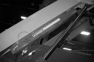
A falling lift arm could result in severe injury or death.
If the lift arm must be left in the raised position, BE SURE to properly apply the lift arm support device.
The operator must not leave the operator's position if the lift arm is in the raised position unless the lift arm support device is properly applied. WARNING
A second person on the outside of the machine is required to assist with applying the lift arm support.
Engage Lift Arm Support
Model 1750RT (Serial Numbers 131001 and Up)
Model 2100RT (Serial Numbers 241001 and Up)
Model 2500RT (All Serial Numbers)
1.Empty and remove the attachment.
2.Bring the machine to a complete stop on a level surface.
3.Raise the lift arm as high as it will go.
4.Move the drive controls to the neutral position.
5.Shut off the engine.
6.Move the lift/tilt controls to verify that the controls do not cause movement of the lift arm and hitch plate.
7.Raise the safety bars/arm rests to apply the parking brake and lock out the hydraulic controls.
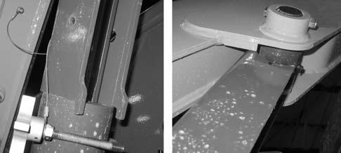
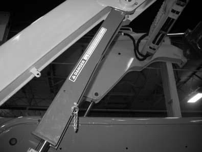
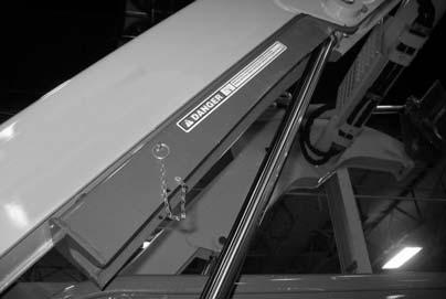
8.Stay in the machine sitting in the operator’s position. A second person, on the outside of the machine, must: a.Remove retaining fastener (Y, Fig. 87) securing lift arm support (Z) in the storage position. b.Position the lift arm support (Z, Fig. 88) over the lift arm cylinder rod (X, Fig. 87 and Fig. 89). c.Position the lift arm support with the curved end (E, Fig. 89) of the support tight against the end of the cylinder rod (P), and tabs (T) on the support hooked over cylinder tube head (C) as shown.
9.Start the machine and lower the lift arm against lift arm support (Z). Verify that lift arm suppport (Z) is properly positioned as shown in Fig. 89.
Warning
The lift arm support device must be properly positioned to prevent the lift arm from falling, which could result in severe injury or death.
10.Shut off the engine.
11.Move the lift/tilt controls to verify that the controls do not cause movement of the lift arm and hitch plate.
12.Raise the safety bars/arm rests to apply the parking brake and lock out the hydraulic controls.
13.Unfasten the seat belt, remove the ignition key and take it with you. Exit the machine using the hand-holds.
Model 1750RT (Serial Numbers 131001 and before) Model 2100RT (Serial Numbers 241001 and before)
1.Empty and remove the attachment.
2.Bring the machine to a complete stop on a level surface.
3.Raise the lift arm as high as it will go.
4.Move the drive controls to the neutral position.
5.Shut off the engine.
6.Move the lift/tilt controls to verify that the controls do not cause movement of the lift arm and hitch plate.
7.Raise the safety bars/arm rests to apply the parking brake and lock out the hydraulic controls.
8.Stay in the machine sitting in the operator’s position. A second person, on the outside of the machine, must: a.Remove retaining pin (Y, Fig. 90) securing lift arm support (Z) in the storage position. b.Position the lift arm support (Z, Fig. 91) over the lift arm cylinder rod (X, Fig. 90 and Fig. 91). c.Insert the retaining pin (Y, Fig. 92) through the lift arm support (Z) so it passes under the lift arm cylinder rod (X).
10.Shut off the engine.
11.Move the lift/tilt controls to verify that the controls do not cause movement of the lift arm and hitch plate.
12.Raise the safety bars/arm rests to apply the parking brake and lock out the hydraulic controls.
13.Unfasten the seat belt, remove the ignition key and take it with you. Exit the machine using the hand-holds.
Release Lift Arm Support
Model 1750RT (Serial Numbers 30871 and Up)
Model 2100RT (Serial Numbers 40421 and Up)
Model 2500RT (All Serial Numbers)
Warning
A second person on the outside of the machine is required to assist with disengaging the lift arm support.
1.Start the engine and raise the lift arm as high as it will go.
2.Move the drive controls to the neutral position.
3.Shut off the engine.
4.Move the lift/tilt controls to verify that the controls do not cause movement of the lift arm and hitch plate.
5.Raise the safety bars/arm rests to apply the parking brake and lock out the hydraulic controls.
6.Stay in the machine in the operator’s position. A second person, on the outside of the machine, must: a.Remove lift arm support (Z, Fig. 93) from the cylinder rod.

7.Have the second person stand away from the machine and lower the lift arm to the ground.
8.Securely insert notch (F, Fig. 94) on lift arm support (Z) into retaining hook (N) on the lift arm. Secure lift arm support (Z) in the storage position using retaining fastener (Y).
Model 1750RT (Serial Numbers 30870 and before) / Model 2100RT (Serial Numbers 40420 and before)
Warning
A second person on the outside of the machine is required to assist with disengaging the lift arm support.
1.Start the engine and raise the lift arm as high as it will go.
2.Move the drive controls to the neutral position.
3.Shut off the engine.
4.Move the lift/tilt controls to verify that the controls do not cause movement of the lift arm and hitch plate.
5.Raise the safety bars/arm rests to apply the parking brake and lock out the hydraulic controls.
6.Stay in the machine in the operator’s position. A second person, on the outside of the machine, must: a.Remove retaining pin (Y, Fig. 95) securing lift arm support (Z) in the support position.
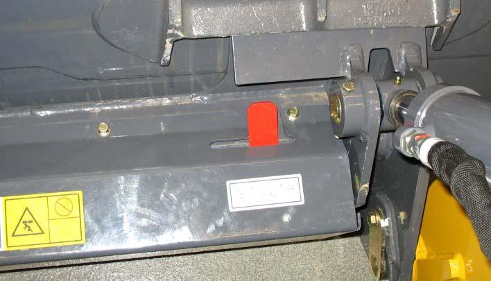
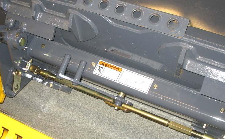
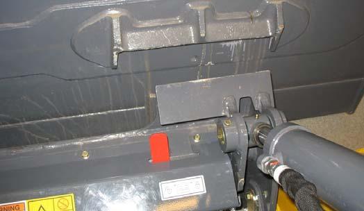
Connecting/Disconnecting Attachments
Connecting Attachments
1.Place the attachment lock into the unlocked position (Fig. 97):
•Power-A-Tach® system hitch – Press the bottom of hitch lock switch (I) until safety flags (H) have moved all the way in.
•Manual attachment hitch – move hitch lock lever all the way to the right (G).
7.Have the second person stand away from the machine and lower the lift arm to the ground.
8.Position the lift arm support (Z, Fig. 96) into the storage position and insert the retaining pin (Y) through the lift arm support (Z) and through the hole in the storage bracket to hold the lift arm support in the storage position.
2.Tilt the attachment plate forward and drive the machine straight forward toward the back of the attachment.
3.Lower the lift arm so tabs (J) on the top of the attachment plate are aligned just under hooks (K) on the back of the attachment.
4.Tilt the attachment plate back until tabs (J) on the top of the attachment plate are engaged against hooks (K) on the back of the attachment.
5.Raise the lift arm slightly until the attachment is hanging from hooks (K) and tabs (J) are firmly inserted into the hooks. Tilt the attachment plate back, if necessary, so the back of the attachment is resting flat against the attachment plate.
6.Place the attachment lock into the locked position (Fig. 98):
•Power-A-Tach® system hitch – Press the top of hitch lock switch (I) until safety flags (H) have moved all the way out.
•Manual attachment hitch – Perform the “Mandatory Safety Shutdown Procedure” on page22 and move hitch lock lever all the way to the left (G).
7.Make sure the locking pins (F, Fig. 99) are fully engaged down through the holes in the attachment.
Warning
To prevent unexpected release of the attachment from the hitch, be sure to properly secure the hitch latch pins by hitch lock lever (G, Fig. 98) all the way to the left (manual AllTach® hitch) or by ensuring that the safety flags (H, Fig. 98) are all the way to the outside (PowerA-Tach® hitch).
Locking pins (F) must be fully engaged through the holes in the attachment frame before using the attachment. The attachment could fall off if it is not locked on the hitch and cause serious injury or death.
Disconnecting Attachments
Warning
Position the attachment so that after disconnecting the attachment will stand safely and not tip over. Serious injury can occur if an attachment tips over onto a person.
1.Empty the attachment and drive to a open, level area to disconnect the attachment.
2.Lower the attachment to the ground.
3.Place the attachment lock into the unlocked position (Fig. 100):
•Power-A-Tach® system hitch – Press the bottom of hitch lock switch (I) until safety flags (H) have moved all the way in.
•Manual attachment hitch – Perform the “Mandatory Safety Shutdown Procedure” on page22 and move hitch lock lever all the way to the right (G).
Powering Attachments with Hydraulic Function
Hydraulically-powered attachments are powered using the auxiliary hydraulics circuits.

Connecting Hydraulic Attachments to the Auxiliary Hydraulic Circuits
IMPORTANT: Connect hydraulically-powered attachment hoses to the auxiliary circuits after the attachment is secured to the hitch.
Disconnect hydraulically-powered attachment hoses from the auxiliary circuits before removing the attachment from the hitch.
NOTE: The connection procedure is the same for both the normal and the optional high-flow auxiliary hydraulic circuits.
Caution
Only connect high-flow attachment couplers to the high-flow auxiliary couplers.
1.Empty the attachment and lower it to the ground.
4.Lower the lift arm until tabs (J) on top of the attachment plate disengage out of hooks (K) on the back of the attachment.
5.Look behind you for bystanders and obstacles. Drive straight back in reverse away from the attachment.
2.Shut off the engine and turn off the ignition. Remove the ignition key and take it with you.
3.Raise the safety bars/arm rests to apply the parking brake.
4.Clean the hydraulic connections on the hoses and the connections.
5.Relieve the pressure in the standard auxiliary hydraulics circuit by pushing the attachment coupler firmly into the auxiliary coupler.
6.Continue to push the hose connections firmly onto the auxiliary hydraulic connections until they snap into place.
Caution
Route the hydraulic hoses so they do not get pinched when the attachment is tilted forward and back. Damaged or burst hydraulic hoses could result.
IMPORTANT: Always check hydraulic function of the attachment before use, to make sure the hydraulic hoses have not been installed in reverse.
NOTE: Pressure build-up caused by heat in hydraulic attachments left in direct sunlight can make it difficult to connect the quick-couplers to the fittings on the attachment.
Disconnecting Hydraulic Attachments from the Auxiliary Hydraulics Circuit
1.Empty the attachment and lower it to the ground.
2.Shut off the engine and turn off the ignition. Remove the ignition key and take it with you.
3.Raise the safety bars/arm rests to apply the parking brake.
4.Push on the hose connection locking rings until the hose connections release.
Auxiliary Hydraulics Operation
Standard-Flow Auxiliary Hydraulics Control
The toggle and trigger switches (A and B, Fig. 102) on the right joystick controls standard-flow auxiliary hydraulics.
Press the top (C) of toggle switch (A) to activate auxiliary hydraulics flow in one direction. Flow control is proportional: the flow rate increases as the toggle switch is moved further. Release the switch to stop the flow.
Press the bottom (D) of toggle switch (A) to activate auxiliary hydraulics flow in the opposite direction. Flow control is proportional: the flow rate increases as the toggle switch is moved further. Release the switch to stop the flow.
For continuous flow:
1.Move toggle switch (A) as far as it will go either forward or back – depending upon what direction flow is required.
2.While holding the toggle switch (A) at the full forward or full reverse position, press trigger button (B). Release trigger button first (B), then release toggle switch (A).
NOTE: Standard flow auxiliary hydraulics continuous flow can only be activated if toggle switch (A) is held in either the FULL forward or FULL reverse position.
To stop continuous standard-flow, press and release trigger switch (B).
NOTE: Standard flow auxiliary hydraulics will remain in continuous flow with the safety bars/arm rests the raised position, the operator’s seat unoccupied and the cab door open.
NOTE: When ignition power is interrupted, auxiliary hydraulic function is reset to OFF.
High-Flow Auxiliary Hydraulics Control (Option)
The optional high-flow hydraulics connections are located on the right side of the machine. See Fig. 101 on page107.
Press and release the top (G, Fig. 103) of the highflow toggle switch (K) to activate high-flow auxiliary hydraulics flow in one direction.
Press and release the bottom (J) of the high-flow toggle switch (K) to activate high-flow auxiliary hydraulics flow in the opposite direction.
To stop continuous high-flow, press and release switch (K)
NOTE: Continuous high-flow will stop if the safety bars/arm rests are raised, if the operator’s seat is unoccupied, or if the cab door is opened.
Warning
If the engine should stall for any reason during auxiliary high-flow hydraulics operation, always turn the ignition key all the way counterclockwise to the “OFF” position before restarting the engine according to “Starting the Engine” on page78.
Optional 14-Pin Connector
Optional 14-pin connector (T, Fig. 104) is intended for attachments equipped with 14-pin compliant connections using direct 12 volt actuation control.
NOTE: Contact Manitou Americas for information about approved 14-pin-equipped attachments.
Switch / Pin Assignments
Refer to Fig. 105 and table 3 for details about joystick switches and the associated pins in the 14pin connector.
NOTE: Indicator (L) in the high-flow toggle switch (K) is lit when auxiliary hydraulics high-flow is activated.

NOTE: Depending upon the attachment, an adapter harness may be necessary. Refer to the documentation supplied with the attachment.
Lifting the Machine using a Crane WARNING
The crane and the lifting gear must be adjusted to the proper dimensions. Always lift the machine so it is horizontal when it is raised.
Make sure the crane and the lifting gear (cables, chains) have sufficient load-bearing capacity. The crane and the lifting gear must be adjusted to the proper dimensions.
Secure the machine against unintentional movement!
Keep clear of suspended loads.
Never lift with anyone in or on the machine.
Securely fasten the lifting gear to the machine at the designated lift points.
The crane lifting crew must include experienced crane operators only.
Lift the machine only with no attachments, with the exception that the standard bucket can remain attached. The bucket must be empty and set to transport position. See “Attachment Transport Position” on page96.
Crane Lifting Preparation
IMPORTANT: Crane handling requires lifting gear with a spreader bar with 4 ropes, chains, etc.
1.If a bucket is attached, make sure it is emptied. Tilt the bucket back.
2.Lower the lift arm.
3.Raise the arm rests/safety bars to apply the parking brake and lock out the hydraulic functions.
4.Turn off the engine and remove the ignition key.
5.If equipped, close and lock the cab door. Do not allow anyone to stay in the cab.
6.Close the doors and the engine cover.
7.Connect spreader bar and chains to front and rear lift points as shown. The spreader bar length should allow for the lift chains to be as vertical as possible during lifting. The lifting chain lengths should allow for lifting the machine as level as possible.
Loading and Transporting the Machine on a Transport Vehicle
Warning
Do not exceed the transport vehicle’s gross weight rating and the gross axle weight rating when loading and transporting the machine. The transport vehicle must have sufficient capacity for the size and weight of the machine. See “Specifications” on page37.
Make sure the load does not fall short of the minimum axle load of the steering axle, otherwise the transport vehicle’s steering could be seriously affected.
Remove any mud, snow or ice from the tracks on the machine to prevent slipping.
Position the machine at the lowest possible position on the transport platform, with the center of gravity of the load over center line of the transport vehicle. Distribute partial loads to ensure an even load on the axles on the transport vehicle.
Caution
Do not fasten the lifting gear to the cab to crane lift the machine.
8.Carefully raise the machine, keeping it as level as possible.
Secure the machine properly so it cannot slip, slide, roll, tip over or fall, or cause the transport vehicle to tip over under transport conditions. Use anti-slip bases and linings, load-securing straps and chains, clamping beams, protective paddings, nets, edge protectors, etc. as needed to properly secure the load. Consider all possible transport conditions such as: heavy braking, evasive maneuvers, and uneven or rough roadways.
Adjust transport speed to the load, to the road/ traffic conditions and to the handling of the transport vehicle.
Always use the proper tie-down points when using straps and chains. See “Component Identification” on page15.
Loading and Securing the Machine WARNING
Secure the loading ramps to the transport vehicle before loading. Position the loading ramps at the shallowest possible angle. Do not exceed an angle of 15°. Only use ramps with anti-skid surfaces.
Make sure the loading area is clear and access to it is not obstructed.
Make sure the driver of the transport vehicle knows the overall height, width and weight of the vehicle, including the loaded machine, before starting transport.
Know and follow the legal transport regulations for the area in which the transport will occur.
Make sure the loading ramps are free of mud, oil, grease, snow, ice, etc.
Know and follow the legal transport regulations for the area in which the transport will occur.
4.Slowly and carefully drive the machine in reverse onto the transport vehicle, with the bucket end facing down the ramp.
5.Do not adjust travel direction while traveling on the ramps. Instead, drive down off of the ramps, and re-align the machine with the ramps.
6.Position the machine at the lowest possible position on the transport platform, with the center of gravity of the load over center line of the transport vehicle.
7.Lower the bucket onto the loading area.
8.Stop the engine.
9.Raise the arm rests/safety bars to apply the parking brake and lock out the hydraulic functions.
10.Remove the ignition key.
11.Do not allow anyone to stay in the cab.
12.Close the doors and the engine cover.
13.Tie down the machine as follows: a.Make sure the authorized maximum height is not exceeded. b.Place blocks in front and behind tracks to prevent movement. c.Securely strap the machine at the tie-down points (Fig. 108) to the platform. Use only belts or chains of sufficient capacity.
1.Check the engine oil. The oil level must be at the “MAX” mark on the dipstick. Add oil if needed.
IMPORTANT: When loading and driving on ramps, the engine can be damaged if the engine oil level is too low.
2.Start the engine.
3.Raise the hitch plate/attachment enough so that it will not touch the loading ramps.
IMPORTANT: Before transporting the machine through heavy rain, close off the exhaust pipe with a cap or suitable adhesive tape.
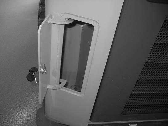
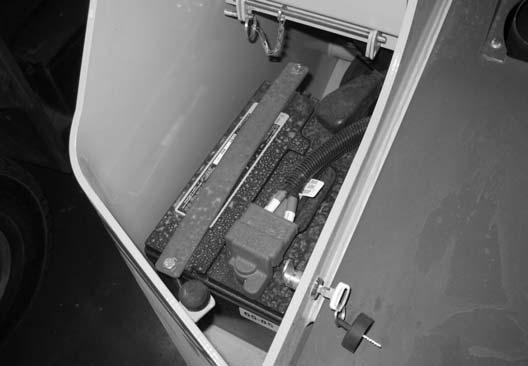
Storage Box
The machine is equipped with a locking storage box (Fig. 109) at the left rear corner of the machine. Use