1 minute read
1750RT/2100RT interim Tier 4 Engine Removal/Installation


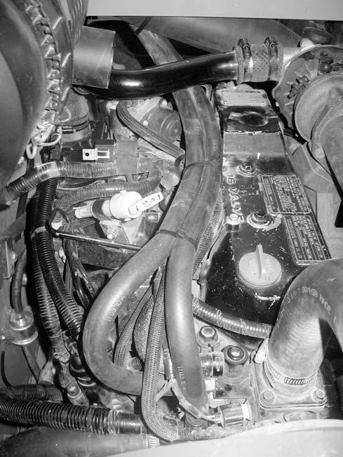
44.Disconnect heater return hose (U, Fig. 417) from the coolant pump.
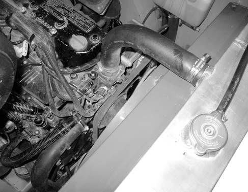
47.Loosen clamp (I, Fig. 422), and disconnect upper radiator/coolant hose (J) from the radiator.
48.Loosen clamp (K) and disconnect lower coolant hose (L) from the coolant pump.
49.Loosen clamp (M) and disconnect overflow hose (N) from the radiator filler neck.
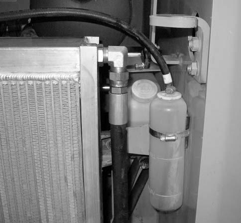
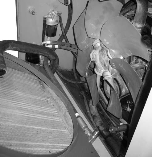
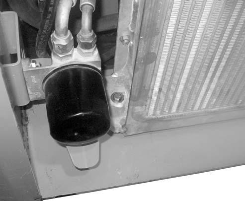
50.Disconnect, cap, and plug hydraulic hose (O, Fig. 423) from hydraulic oil return filter head (A).
45.Disconnect heater supply hose (V) from thermostat housing,
46.Remove cable ties (W).
51.Disconnect hydraulic hose (P, Fig. 424) from the radiator (Q). Cap and plug hydraulic hose (P) and fitting (B).
52.Support radiator (Q Fig. 425) using an appropriate lifting device.
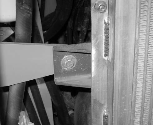
54.On both sides of the radiator (Q), remove locknut (T, Fig. 426), screw (U), flat washer (V), and large flat washer (W).
53.Remove two screws (R) and flat washers (S) from the bottom of the radiator (Q).
NOTE: Record the location of washers (S) to ensure correct installation.
55.Tilt the top of radiator (Q, Fig. 427) back to gain access to hydraulic hose (X) at the bottom of assembly (Q).
56.Disconnect, cap, and plug the hydraulic hose (X, Fig. 427) and fitting (Y).