Electrical/Control Systems Electrical Control System
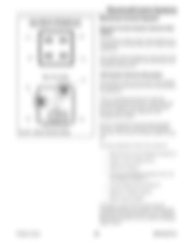
Horn, HVAC Fan, DEF System, and Engine Relays in Fuse/Relay Boxes
Electrical Control System General Information 85
87
The electronic control system in the machine uses a combination of switches/relays and computer-based components.
86
The computer-based components communicate with each other using a Controller Area Network (CAN) communication protocol.
30
CAN System General Information
Main Power Relay 87
The electrical system uses the SAE J1939 standard for Controller Area Network (CAN) communication and diagnostics.
30
86
CAN is a message-based protocol, allowing communication between devices without the need for a host computer. It provides communication between control system components used throughout the machine. 85
Devices communicate with each other through a two-wire, serial bus connection (CAN high and CAN low). The wires are 120 ohm nominal twisted pair.
Fig. 537 – Relay Continuity Testing
The main components of the CAN system are: • Multi-function Control Module (Controller 3) • Engine Control Module (ECU) • Main Power Relay 2 • Lift Arm and Standard Auxiliary Flow Control Module (Controller 1) • Control Module (R) (Controller 2) • High-Flow Module (Option) • Multi-Function Display CAN allows various devices on the network coordinate functions. For example, CAN messages generated by the multi-function control module are acted upon by the ECU (or vice-versa) to coordinate engine control. Printed in U.S.A.
299
50940165/C0718


