Hydraulic System Tests 10. If neither lift cylinder shows signs of external or internal leakage, and the lift arm still drifts, the problem could be due to hydraulic leaks between the control valve and the lift cylinders. Check all hydraulic connections thoroughly. The problem could also be in either the main control valve or the Hydraglide/ride control valve.
2. Lift the ROPS/FOPS according to “Raising ROPS/FOPS” on page 140. 3. Loosen the adjustment screw locknut on the appropriate relief valve. 4. Adjust relief valve pressure using the adjustment screw. NOTE: Tightening (rotating clockwise) the
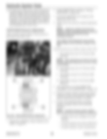
Lift/Tilt Relief Pressure Adjustment
adjustment screw increases pressure; loosening (rotating counter-clockwise) the screw decreases pressure
Adjust rod/base lift/tilt cylinder relief pressures at the control valve (Fig. 535):
One rotation of the adjustment screw equals approximately 30 bar (435 psi) change in pressure.
A B
Correct pressures are as follows (refer to (Fig. 535): A. Tilt cylinder base end: 237-245 bar (34483552 psi). NOTE: Early machines do not have a tilt cylinder base end relief adjustment and have a plug in this location.
D C
B. Lift cylinder base end: 237-245 bar (34483552 psi). C. Tilt cylinder rod end: 237-245 bar (34483552 psi). A
D. Lift cylinder rod end: 138-142 bar (20002060 psi).
B
5. After adjustment, lower the ROPS/FOPS according to “Lower ROPS/FOPS” on page 142. 6. Perform cylinder rod/base end pressure tests as required to verify correct pressure. Repeat the pressure adjustment procedure if required.
C
D
7. If relief valve adjustment does not change pressure readings, check for the following problems: NOTE: Possible hydraulic system malfunctions include but are not limited to the following:
Fig. 535 – Tilt/Lift Relief Pressure Adjustment
• Possible relief valve cartridge valve malfunction.
1. Perform the “Mandatory Safety Shutdown Procedure” on page 22.
• Possible hydraulic gear pump malfunction. • Possible hydraulic system contamination.
50940165/C0718
296
Printed in U.S.A.


