Hydraulic Equipment 9. Connect wiring connectors (N, O, P, Q, R and S, Fig. 505) to the same locations as noted during removal.
NOTE: If the foot well was tilted foward to provide access during pump removal/installation, tilt it back into place and secure using screws (F, Fig. 506).
Later Machines N F
F
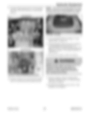
Q R O S Fig. 506 – Foot Well
11. Lower the ROPS/FOPS according to “Lower ROPS/FOPS” on page 142. P
12. Fill the hydraulic system reservoir according to “Changing Hydraulic Oil and Filter” on page 132. Refer to “Fluids/Lubricants Types and Capacities” on page 37 for proper hydraulic oil specifications.
Early Machines N
13. Reconnect the negative cable to the battery.
O
S
WARNING
T
R
P
NEVER use your hands to search for hydraulic fluid and coolant leaks. Use a piece of cardboard or paper. Escaping fluid under pressure can be invisible and penetrate the skin, causing serious injury.
Q
Fig. 505 – Connect Pump Wiring Connectors
14. Start the machine. Check for proper pump operation, hydraulic leaks, etc. Stop the engine and repair as required.
10. Connect connector (T) to the fuel tank sending unit if it was disconnected for pump removal.
15. Re-check the hydraulic system oil level. Add hydraulic oil as required.
Printed in U.S.A.
275
50940165/C0718


