Hydraulic Equipment 3. Lift the hydrostatic pump with an appropriate lifting device. NOTE: The hydrostatic pump weighs approximately 90-113 kg (200-250 lbs.).
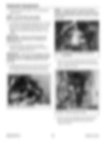
NOTE: The gear pump for machines with the high-flow auxiliary option is shown in Fig. 502. Gear pump for standard flow auxiliary hydraulics is shown in Fig. 503.
4. Carefully lift hydrostatic pump (R, Fig. 501) into place using an appropriate lifting device. Align the splines on the pump input shaft with the adapter, and install the pump assembly on the adapter.
V
IMPORTANT: Use new mounting screws (S) [Manitou part # 273400] when re-installing the hydrostatic pump.
5. Secure the pump assembly to the engine flywheel housing using fasteners (S). Torque screws to 102 Nm (75 lb.-ft.).
W
Fig. 503 – Standard Flow Auxiliary Hydraulics Gear Pump
IMPORTANT: Use a new O-ring [Manitou part # 132248] and new mounting screws [Manitou part # 50280004] when re-installing the gear pump (W, Fig. 502).
6. Install gear pump (W, Fig. 502) onto the front of the hydrostatic pump and secure with screws (V). Torque screws (V) to 102 Nm (75 lb.-ft.).
7. Remove the caps and plugs and connect hoses (D, E, F, G, H I and J, Fig. 504) to the hydrostatic pump. Tighten securely
D E W
J F
V
I G H K M W
Fig. 502 – Gear Pump Installation L Fig. 504 – Connect Hydraulic Hoses
8. Remove the caps and plugs and connect hoses (K, L and M) to hydraulic gear pump (W). Tighten securely.
50940165/C0718
274
Printed in U.S.A.


