Hydraulic Equipment • Feedback/Signal voltage (between center wire in connector and ground): 2.48 - 2.52V when pump is in neutral; 0.2V - 4.8V with pump at maximum forward displacement (code # 1-6).
Forward and Reverse Solenoids The swash plates are moved using electrohydaulic proportional valves. Solenoids (H, I, J and K) port oil to the servo pistons when they are energized. • Solenoid (H): Left track drive reverse • Solenoid (I): Right track drive reverse • Solenoid (J): Left track drive forward • Solenoid (K): Right track drive forward
3. Disconnect the negative cable from the battery. Secure the negative cable away from the battery terminals. 4. Drain the hydraulic reservoir system according to “Changing Hydraulic Oil and Filter” on page 132. IMPORTANT: Always dispose of hydraulic fluids according to environmental laws or take to a recycling center for proper disposal. DO NOT pour onto the ground or down a drain.
NOTE: Hydraulic reservoir capacity: Model 1750RT – approximately 41.5 L (11 gals.); Model 2500RT/2100RT – approximately 53 L (14 gals.).
5. Raise the ROPS/FOPS according to “Raising ROPS/FOPS” on page 140.
Test solenoid resistance between the two connector pins. Resistance should measure 2.0 - 3.0 ohms at 70F (code # 7-10).
Hydrostatic Pump Removal IMPORTANT: Park the machine where the lift arm can be supported with a overhead hoist or similar device. NOTE: Depending upon on the lifting device used, it may be necessary to remove the ROPS/FOPS to allow access to the pump assembly. See “ROPS/ FOPS Removal” on page 167.
WARNING Always secure the ROPS/FOPS in the tilted position with the ROPS/FOPS tilt support device properly engaged. Never allow anyone under the ROPS/FOPS if the tilt support device is not properly engaged.
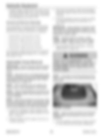
NOTE: If necessary to provide clearance for the pump, remove screws (F, Fig. 495) and tilt the foot well forward.
NOTE: Some machines may vary slightly from what is shown in the photographs in this section. NOTE: Label all hoses/electrical connections and note their locations before disconnecting to ensure correct installation.
F
NOTE: Some loss of hydraulic oil will occur when disconnecting hydraulic hoses. Use absorbent mats to catch any dripping oil when disconnecting hoses. Cap and plug hydraulic lines after disconnecting. 1. Complete the Mandatory Safety Shutdown Procedure. See “Mandatory Safety Shutdown Procedure” on page 22. 2. Operate controls with the engine off, power on, to relieve pressure.
50940165/C0718
F
Fig. 495 – Foot Well
NOTE: Label all wiring connectors and note their locations before disconnecting to ensure correct installation. 6. On early machines, disconnect wiring connector (A, Fig. 496) from the fuel tank sending unit.
270
Printed in U.S.A.


