1750RT/2100RT interim Tier 4 Engine Removal/Installation 62. Route engine compartment access door harness (E, Fig. 479) into the engine compartment.
a. Connect supply (Q, Fig. 481) and return (R) air conditioning lines to the air conditioning condenser.
Q
E R
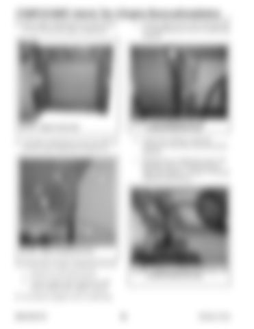
Fig. 481 – Air Conditioning Lines (Air Conditioned Machines Only)
Fig. 479 – Engine Access Door
b. Connect the condenser cooling fan connector (S, Fig. 482) to the main harness connector.
63. Lift engine compartment cover (I, Fig. 480) into position using an appropriate lifting device.
M
c. Recharge the air conditioning system with refrigerant. Refer to “Fluids/Lubricants Types and Capacities” on page 37 for proper refrigerant specifications.
I
J S
K
L
Fig. 480 – Engine Compartment Cover
64. On both sides of engine compartment cover (I): Fig. 482 – Condenser Cooling Fan Connector (Air Conditioned Machines Only)
a. Install pin (J) and spring clip (K). b. Connect support strut to bracket (L) and secure using nut (M). Tighten securely. 65. On machines equipped with air conditioning:
50940165/C0718
260
Printed in U.S.A.


