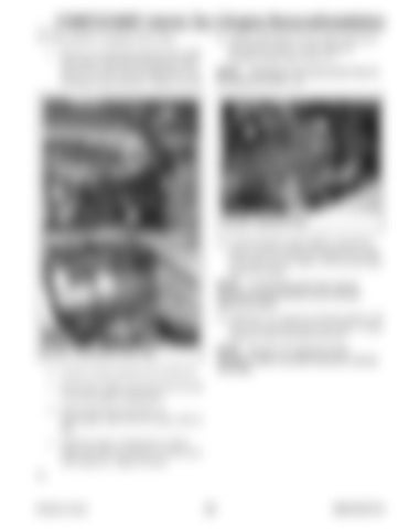
1750RT/2100RT interim Tier 4 Engine Removal/Installation 39. If the machine is equipped with a turbo: a. Remove covering protecting the turbo intake from debris and install turbocharger intake tube (G, Fig. 464). Secure intake tube to turbocharger using clamp (H). Tighten securely.
41. Attach a lift bracket (X, Fig. 465) to the top of the hydraulic pump, to allow lifting the hydraulic pump using a hoist (Y). NOTE: Threading for mounting bracket holes for lift bracket (X) is M12-1.75.
K X Y
L M I J
H
G
Fig. 465 – Hydraulic Pump
42. Lift the hydraulic pump slightly, and pull the pump rearward, meshing the splined driveshaft in the pump into the engine. Pull the pump tight against the engine.
G
NOTE: A come-along hand winch may be required to pull the hydraulic pump rearward against the engine. X
43. Install new 1/2” capscrews (S) and washers, and secure the hydraulic pump to the engine. Torque capscrews (S) to 101 Nm (75 lb.-ft.)
Y
NOTE: Use new 1/2” capscrews (S) for installation. Refer to the parts manual for ordering information.
Fig. 464 – Turbocharger Intake Tube
b. Connect wiring connector (I) to sensor (J). c. Route heater supply and return hoses (K and L) into the engine compartment. d. Secure heater hoses (K and L) to turbocharger intake tube (G) using a cable tie (M). e. Inside the engine compartment, connect intake tube (G) to air cleaner (Y) and secure with clamp (X). Tighten securely. 40.
Printed in U.S.A.
255
50940165/C0718


