1750RT/2100RT interim Tier 4 Engine Removal/Installation 29. Lower the ROPS/FOPS according to “Lower ROPS/FOPS” on page 142.
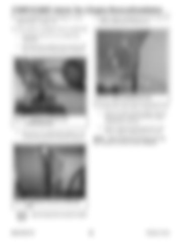
31. Support engine compartment cover (A, Fig. 413) using an appropriate lifting device.
30. If the machine is equipped with air conditioning: a. Discharge and recover air conditioning refrigerant. B
a. Disconnect the condenser fan connector (B, Fig. 411) from the main harness connector.
A
E
B D
C
Fig. 413 – Engine Compartment Cover
32. On both sides of the engine compartment cover: a. Remove nut (B) securing support strut (C), and disconnect support strut from engine compartment cover (A).
Fig. 411 – Condenser Connector (Air Conditioning Only)
b. Disconnect air conditioning supply (C, Fig. 3) and return (D) lines from the condenser.
b. Remove spring clip (D) and pin (E), and remove engine compartment cover (A). NOTE: Label all electrical connectors and note their locations to ensure correct installation.
C
D
Fig. 412 – Condenser Lines (Air Conditioning Only)
NOTE: Cap and plug lines to prevent contamination.
50940165/C0718
238
Printed in U.S.A.


