Models 1750RT/2100RT Tier 4 Engine Removal/Installation Tier 4 Engine Installation Model 1750RT (S/N 131001 and Up) Model 2100RT (S/N 241001 and Up) IMPORTANT: Always verify electrical connec-
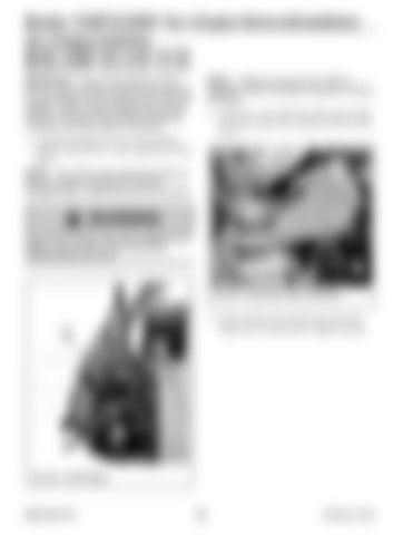
NOTE: Install new screws (B, Fig. 355) for
tions are sound and strain relieved when static and to accommodate moving components and machine operation. Route, tie and clamp all wires and connections to avoid pinching, chaffing and damage consistent with factory design and practice.
installation. Refer to the parts manuals for ordering information.
1. Carefully lift engine (K, Fig. 354) into place using an engine hoist or other appropriate lifting device.
2. Install new screws (B) and washers (C) in both rear motor mounts (D). Torque to 298 Nm (220 lb.-ft.).
B
NOTE: Use caution when positioning engine (K)
C G
F
inside the engine compartment to prevent damaging hoses, components and wire harnesses.
WARNING Keep hands and feet clear when positioning the engine in the machine. Severe pinching/ crushing injury can occur. X D
E
Fig. 355 – Install Motor Mount Hardware
K
3. Secure fuel line (X) to left motor mount (D) using screw (F) and nut (G). Tighten securely.
Fig. 354 – Install Engine
50940164/C0718
220
Printed in U.S.A.


