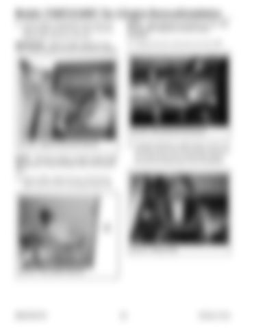
Models 1750RT/2100RT Tier 4 Engine Removal/Installation 41. Lift the engine compartment access door just high enough for pins (P, Fig. 334) to clear the brackets (Q), and remove the door.
NOTE: Label electrical connections (Z, Fig. 336) and note their locations to ensure correct installation.
IMPORTANT: There is a fiber washer (R, Fig.
43. Unplug electrical connections (Z) from DPF.
335) located between the door and frame brackets. Z
Q Z
P Fig. 336 – DPF Electrical Connections Fig. 334 – Engine Access Door Removal
NOTE: The door is heavy. A hoist or other similar lifting device is recommended when removing the door.
44. To prevent damage to exhaust pipe (A, Fig. 337) and DPF, remove nuts (B) securing exhaust pipe (A) to DPF and remove exhaust pipe. Retain nuts (B) and exhaust pipe (A) for installation.
42. Remove fiber washer (R, Fig. 335) from the upper and lower door mounting brackets (Q).
A R
B
Fig. 337 – Exhaust Pipe Q
Fig. 335 – Fiber Washer Removal
50940164/C0718
214
Printed in U.S.A.


