Models 1750RT/2100RT Tier 4 Engine Removal/Installation 26. Remove screws (H, Fig. 322) and flat washers (I) from both front motor mounts. Discard screws (H), but retain washers for installation. NOTE: Screws (H) should be replaced for installation. Refer to the parts manual for ordering information.
J
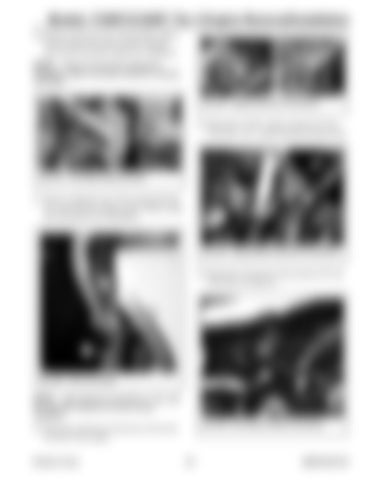
Fig. 324 – Engine Electrical Connections I
29. Disconnect “C182” engine connector (F, Fig. 325) and “C181” starter solenoid connector (G). H
Fig. 322 – Front Motor Mount Screws F G
27. Remove clamp (K, Fig. 323) securing fuel line (L) to the left front engine mount. Retain clamp (K) and fasteners for installation.
Fig. 325 – Engine/Starter Electrical Connections
30. Disconnect oil pressure ring connector (H, Fig. 326) from oil sender (I).
K
L
H
Fig. 323 – Fuel Line Clamp
I
NOTE: Label electrical connections (J, Fig. 324) and note their locations to ensure correct installation. Fig. 326 – Oil Pressure Switch Connection
28. Disconnect electrical connections (J) from the left front of the engine.
Printed in U.S.A.
211
50940164/C0718


