Models 1750RT/2100RT Tier 4 Engine Removal/Installation 8. Drain the fuel tank using suction.
WARNING
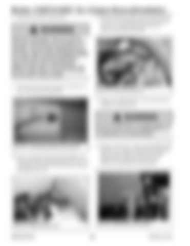
11. Tip the fuel tank to allow access to the fuel line (D, Fig. 315) exiting the front of the fuel tank. Loosen the clamp securing fuel line (D). Remove and cap fuel line (D).
Diesel fuel is flammable. Keep the machine away from open flames. Do not smoke or have any spark- or flame-producing equipment or materials in the area when working around the fuel system. Wipe up spills immediately. NEVER use a shop rag to catch fuel draining fuel. Vapors from the rag are flammable and explosive. Work only in a well ventilated area. Failure to follow these instructions can cause fire and result in injury or death.
D
9. Disconnect fuel sender electrical connector (A, Fig. 312) from fuel sender (B).
Fig. 315 – Front Fuel Tank Line
12. Support the ROPS/FOPS in the raised position using an overhead hoist.
A
WARNING Secure the ROPS/FOPS in the tilted position. Do not allow anyone under the ROPS/FOPS if it is not supported in the raised position.
B
Fig. 313 – Fuel Sender Electrical Connection
10. Have an assitant lift the fuel tank slightly and loosen the clamp securing fuel line (C, Fig. 314) exiting the rear section of the fuel tank. Remove and cap fuel line (C).
13. Remove nut (X, Fig. 316) securing ROPS/FOPS prop bar (Y). Remove hardware securing prop bar (Y) to the bracket on the bottom of the ROPS/FOPS, noting the position of the hardware components for reassembly.
X C
Y
Fig. 316 – ROPS/FOPS Tilt Prop Bar
Fig. 314 – Rear Fuel Tank Line
50940164/C0718
208
Printed in U.S.A.


