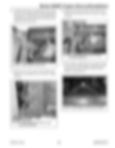
Model 2500RT Engine Removal/Installation 42. Carefully lift engine compartment access door (W, Fig. 304) into position using an appropriate lifting device. Align pins (X) with the holes in mounting bracket (Y) and lower the door until the pins seat in the holes.
44. Install screw (B, Fig. 306), 2 flat washers (C), and nut (D) through the hole in the pin. Tighten securely.
C
B
W
Y C D
Fig. 306 – Install Engine Access Door Upper Mounting Hardware
X
45. Route engine compartment access door harness (L, Fig. 307) into the engine compartment and along the top of the radiator shroud. Secure harness with cable ties.
Fig. 304 – Install Engine Access Door
43. Install screw (Y, Fig. 305), 2 flat washers (Z), and nut (A) through the hole in the pin. Tighten securely.
L Y
Z
Z A Fig. 307 – Route Engine Access Door Harness
Fig. 305 – Install Engine Access Door Lower Mounting Hardware
Printed in U.S.A.
203
50940165/C0718


