Model 2500RT Engine Removal/Installation 19. Install screw (F, Fig. 285) and washer (G) into the mounting bracket on each side of the radiator/hydraulic oil cooler assembly.
22. Connect rear engine ground cable (J, Fig. 287).
J
G
F
Fig. 287 – Connect Rear Engine Ground Cable
Fig. 285 – Install Lower Radiator/Hydraulic Oil Cooler Mounting Hardware
23. Connect glow plug ground wire (K, Fig. 288).
20. Raise the ROPS/FOPS according to “Raising ROPS/FOPS” on page 140. K
WARNING Secure the ROPS/FOPS in the tilted position. Do not allow anyone under the ROPS/FOPS if the tilt securing mechanism is not in place.
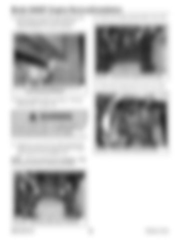
21. Install new screws (H, Fig. 286) and large flat washers (I) into the rear motor mounts. Torque screws (H) to 813 Nm (600 lb.-ft.).
Fig. 288 – Connect Glow Plug Ground Wire
NOTE: Use new screws (H) for installation. Refer to the parts manual for ordering information.
H
H I
I
Fig. 286 – Install Rear Motor Mount Hardware 50940165/C0718
198
Printed in U.S.A.


