Model 2500RT Engine Removal/Installation 7. Support engine compartment cover (A, Fig. 223) using an appropriate lifting device.
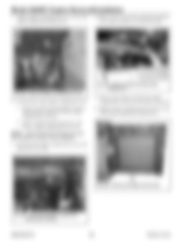
10. Remove tie (L, Fig. 225) securing door harness (Z) to upper hydraulic oil cooler hose (M).
A
L
M
B C E Z
D
Fig. 225 – Remove Upper Oil Cooler Hose Harness Tie Fig. 223 – Remove Engine Compartment Cover
8. On both sides of the engine compartment cover:
11. Remove door harness (Z) from the engine compartment, and secure the harness to the door.
a. Remove nut (B) securing support strut (C), and disconnect support strut from engine compartment cover (A).
12. Support engine compartment access door (I, Fig. 226) using an appropriate lifting device.
b. Remove spring clip (D) and pin (E), and remove engine compartment cover (A). NOTE: Label all electrical connectors and note their locations to ensure correct installation. 9. Disconnect the engine compartment access door harness (K, Fig. 224).
F
I
K
Fig. 226 – Remove the Engine Access Door
Fig. 224 – Disconnect Engine Compartment Access Door Harness
50940165/C0718
182
Printed in U.S.A.


