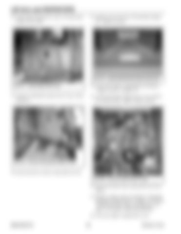
Lift Arm and ROPS/FOPS 18. Install right side panel (A, Fig. 217) and secure using 6 screws (B).
21. Install 2 screws (D, Fig. 219) and flat washers (E). Tighten securely.
D
B
E
B B A Fig. 219 – Install ROPS/FOPS Retaining Screws
22. Access the engine compartment according to “Engine Access” on page 119.
Fig. 217 – Install Right Side Panel
19. Connect windshield washer hose (Y, Fig. 218) to fitting (C).
23. Connect the heater return hose (U, Fig. 220) to the coolant pump. Tighten clamp securely.
C Y
X
X
U
X Fig. 218 – Connect Windshield Washer Hose
20. Secure the hose as shown using cable ties (X). Fig. 220 – Connect Heater Return Hose
24. Secure the heater hoses using cable ties (X) as shown. 25. Fill the cooling system according to “Draining/ Refilling Cooling System” on page 125. Refer to “Fluids/Lubricants Types and Capacities” on page 37 for proper coolant specifications 26. Close the engine compartment covers. 50940165/C0718
178
Printed in U.S.A.


