Lift Arm and ROPS/FOPS 2. On both sides of the ROPS/FOPS:
ROPS/FOPS Installation
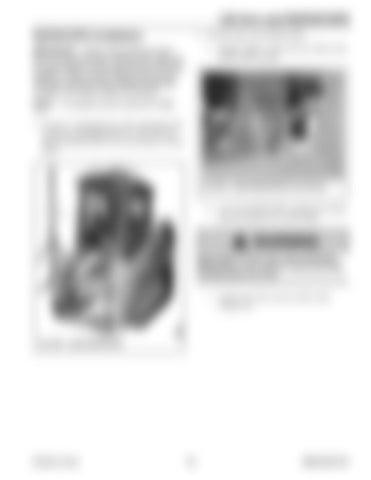
a. Install 2 rubber washers (B, Fig. 206) on the ROPS/FOPS mounts.
IMPORTANT: Always verify electrical connections are sound and strain relieved when static and to accommodate moving components and machine operation. Route, tie and clamp all wires and connections to avoid pinching, chaffing and damage consistent with factory design and practice.
E
NOTE: An assistant may be required for steps 1–3.
F
D F
1. Using an overhead hoist or other appropriate lifting device, lift ROPS/FOPS (A, Fig. 205) and position ROPS/FOPS (A) several inches over the frame.
C C
B Fig. 206 – Install ROPS/FOPS Pivot Screws
b. Lower the ROPS/FOPS, guiding the mounts between brackets (C) on the frame.
A
WARNING Keep hands and feet clear when positioning ROPS/FOPS on the machine. Severe pinching/ crushing injury can occur.
c. Install screw (D), nut (E), and two flat washers (F).
Fig. 205 – Install ROPS/FOPS
Printed in U.S.A.
173
50940165/C0718


