Lift Arm and ROPS/FOPS NOTE: Tilt stop plates (H) need to be
11. Remove cable ties (G).
removed to allow ROPS/FOPS support struts (Y, Fig. 202) to extend to their un-sprung position. Tilt stop plates (H, Fig. 192) prevent premature wear of the ROPS/FOPS support struts.
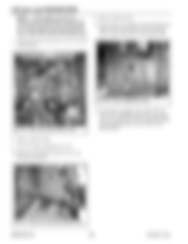
12. If the machine is equipped with heat ducting side panel (I, Fig. 195), remove 6 screws (H) and remove right side panel (I). Move panel aside.
7. Disconnect heater return hose (A, Fig. 193) from coolant pump.
H
H H I
B
Fig. 195 – Remove Right Side Panel A
13. On machines equipped with a splice (M, Fig. 196) in the windsheild washer hose, disconnect the hose at splice (M). Route windshield washer hose (E) through hole (J) at the floor of the ROPS/FOPS.
Fig. 193 – Disconnect Heater Return Hose
8. Remove cable ties (B). 9. Close the engine compartment covers. 10. Disconnect windshield washer hose (E, Fig. 194) from fitting (F).
F E
G
G Fig. 194 – Disconnect Windshield Washer Hose
50940165/C0718
168
Printed in U.S.A.


