Golf 2015 ➤ , Golf Variant 2015 ➤ Engine Mechanical, Fuel Injection and Ignition - Edition 04.2015
2
Engine Oil Cooler
⇒ “2.1 Overview - Engine Oil Cooler”, page 192 . ⇒ “2.2 Engine Oil Cooler, Removing and Installing”, page 192 . ⇒ “2.3 Mechanical Switch Valve, Removing and Installing”, page 194 .
2.1
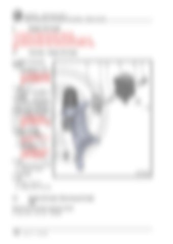
Overview - Engine Oil Cooler
es, in part or in w l purpos hole ercia , is n m m ot p o c erm or e t a itte iv r du rp o nl f e ng
ility ab y li an pt ce
1 - Auxiliary Components Bracket n AG. Volkswagen AG do ❑ Removing and instal‐ es n wage s k l ot g ling. Refer to y Vo ua b d ran ⇒ “1.5 Auxiliary Compo‐ ir se tee o h nents Bracket, Remov‐ t or u ac a ing and ss Installing”, page 53 .
2 - Seal ❑ Replace after removing
rrectness of i t to the co nf o r m spec atio h re n in wit
3 - O-Rings ❑ Replace after removing ❑ Coat with engine oil 4 - Mechanical Switch Valve ❑ Replacing. Refer to ⇒ “2.3 Mechanical Switch Valve, Remov‐ ing and Installing”, page 194 .
ht rig py Co t.
agen lksw Vo by
AG.
c o p yri gh t . C op yi
6 - Seal ❑ Replace after removing ❑ Coat with coolant
thi sd o cu m en
5 - Engine Oil Cooler ❑ See note. Refer to ⇒ “1 Oil Pan/Oil Pump”, page 179 . ❑ Removing and instal‐ ling. Refer to ⇒ “2.2 Engine Oil Cool‐ er, Removing and In‐ stalling”, page 192 . Prote cted by
7 - Connection 8 - Bolt ❑ 8 Nm + 45° turn ❑ Replace after removing
2.2
Engine Oil Cooler, Removing and Instal‐ ling
Special tools and workshop equipment required ♦ Shop Crane - Drip Tray - VAS6208-
192
Rep. Gr.17 - Lubrication


