3 minute read
1.6 Engine Support, Removing and Installing


– Start engine and check whether ribbed belt runs correctly. Tightening Specifications ♦ Refer to ⇒ Body Exterior; Rep. Gr. 66 ; Noise Insulation;
Overview - Noise Insulation .

Caution
Protected by copyriht . Copying fo pivate or co merci al pur po s e s , i n p a r t r o r in w ho le, is not permitted unless authorised by Volkswagen AG. Volkswagen AG does notguarantee or accept any liabilit y wi th res pect t o t h e c o r r e c t n e ss o f in format ion in this document. Copyright by Volkswagen AG. This procedure contains mandatory replaceable parts. Refer to component overview prior to starting procedure. Mandatory Replacement Parts ♦ Bolts - Ribbed Belt Tensioner m Removing – Remove the ribbed belt from the tensioner. Refer to ⇒ “1.2 Ribbed Belt, Removing and Installing”, page 46 . – Remove the bolts -arrows- and pull the ribbed belt tensioning damper -1- off the sub-assembly bracket. Installing Install in reverse order of removal. Note the following: – Install the ribbed belt. Refer to ⇒ “1.2 Ribbed Belt, Removing and Installing”, page 46 . Tightening Specifications ♦ Refer to ⇒ “1.1 Overview - Cylinder Block, Belt Pulley Side”, page 44 . r1.4 Vibration Damper, Removing and Instal‐ling g Special tools and workshop equipment required ♦ Counterhold - Vibration Damper - T10355♦ Locking Pin - T10060A♦ Assembly Tool - T10531Individual components of the Assembly Tool - T10531- : ♦ Counterhold Tool - T10531/1♦ Tensioning Pins - T10531/2♦ Turning Over Tool - T10531/3♦ Collar Nut - T10531/4Golf 2015 ➤ , Golf Variant 2015 ➤ Engine Mechanical, Fuel Injection and Ignition - Edition 04.2015
Golf 2015 ➤ , Golf Variant 2015 ➤ Engine Mechanical, Fuel Injection and Ignition - Edition 04.2015
Caution
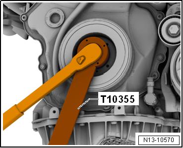
Mandatory Replacement Parts ♦ Bolts - Timing Chain Cover ♦ Bolt - Vibration Damper ♦ O-ring - Vibration Damper The vibration damper bolt -A- connects the vibration damper -1timing chain connection -2- and the crankshaft -3-. Secure the chain sprocket as described as follows to the crankshaft, before removing the vibration damper. Protectd by copyright . Copying fo pivate or co merci al p r po s e s , i n p a r t r o r in w ho le, is not permitted unless authorised by Volkswagen AG. Volkswagen AG does notguarantee or accept any liabilit y wi th res pect t o t h e c o r r e c t n e ss o f in format ion in this document. Copyright by Volkswagen AG. u Remove Vibration Damper – Remove the right wheel housing liner front section. Refer to ⇒ Body Exterior; Rep. Gr. 66 ; Wheel Housing Liner; Front Wheel Housing Liner, Removing and Installing . – Remove the ribbed belt. Refer to ⇒ “1.2 Ribbed Belt, Removing and Installing”, page 46 . – Remove the Locking Pin - T10060A- from the ribbed belt ten‐sioner. m – Turn the vibration damper with the Counterhold - Vibration Damper - T10355- to the Top Dead Center (TDC) point -arrow-. r • The notch on the vibration damper must line up with the arrow marking on the timing chain lower cover. • The marking for the cover is located in the »four-o'clock posi‐tion«. e – Loosen the vibration damper bolt approximately 1/2 turn, to do this use the Counterhold - Vibration Damper - T10355- . – If the vibration damper was turned, correct to TDC.