3 minute read
1.5 Auxiliary Components Bracket, Removing and Installing


Golf 2015 ➤ , Golf Variant 2015 ➤ Engine Mechanical, Fuel Injection and Ignition - Edition 04.2015
6 - Vibration Damper ❑ With ribbed belt pulley ❑ Removing and installing. Refer to ⇒ “1.4 Vibration Damper, Removing and Installing”, page 47 . ❑ Vibration Damper Sealing Ring, Replacing. Refer to ⇒ “2.3 Vibration Damper Sealing Ring, Replacing”, page 112 . 7 - Auxiliary Components Bracket ❑ With oil filter and engine oil cooler ❑ Accessory assembly bracket, removing and installing. Refer to ⇒ “1.5 Auxiliary Components Bracket, Removing and Installing”, page 53 . ❑ Removing and installing the engine oil cooler. Refer to ⇒ “2.2 Engine Oil Cooler, Removing and Installing”, page 192 . 8 - Seal ❑ Replace after removing 9 - Bolt ❑ Replace after removing ❑ Tightening specification and sequence. Refer to ⇒ Fig. ““Accessory Assembly Bracket - Tightening Specifications and Tightening Sequence”“ , page 45 . 10 - Bolt ❑ Tightening specification. Refer to ⇒ Electrical Equipment; Rep. Gr. 27 ; Generator; Overview - Gener‐ator .
11 - Generator ❑ Overview. Refer to ⇒ Electrical Equipment; Rep. Gr. 27 ; Generator; Overview - Generator . 12 - Alignment Sleeves ❑ For A/C compressor 13 - Air Conditioning (A/C) Compressor ❑ Do not remove or disconnect refrigerant lines ❑ Assembly overview. Refer to ⇒ Heating, Ventilation and Air Conditioning; Rep. Gr. 87 ; A/C Compressor; Overview - A/C Compressor Power Unit . 14 - Bolt ❑ Tightening specifications. Refer to ⇒ Heating, Ventilation and Air Conditioning; Rep. Gr. 87 ; A/C Com‐pressor; Overview - A/C Compressor Power Unit .
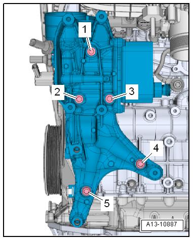
Accessory Assembly Bracket - Tightening Specifications and Tightening Sequence – Mount the accessory assembly bracket and then install the bolt -4- by hand.
Note
Protected by copyright . Copying for piva e or comm rci al p r po s e s , i n p a r t r o r in w ho le, is not permitted unless authorised by Volkswagen AG. Volkswagen AG does notguarantee or accept any liabilit y wi th res pect t o t h e c o r r e c t n e ss o f in format ion in this document. Copyright by Volkswagen AG. u Replace the bolts that were tightened with an additional turn. e – Tighten bolts in 3 stages in -1 to 5- sequence as follows: Step Bolts t Tightening Specification 1. -1 through 5- Tighten by hand 2. -1 through 5- 20 Nm 3. -1 through 5- Turn an additional 90°.
Golf 2015 ➤ , Golf Variant 2015 ➤ Engine Mechanical, Fuel Injection and Ignition - Edition 04.2015

Ribbed Belt Routing 1 - Vibration damper 2 - Ribbed Belt Tensioning Damper 3 - Generator
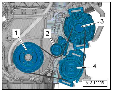
4 - A/C Compressor Protected by copyright . Copying for pivate or co merci al pur po s e s , i n p a r t r o r in w ho le, is not permitted unless authorised by Volkswagen AG. Volkswagen AG does notguarantee or accept any liabilit y wi th res pect t o t h e c o r r e c t n e ss o f in format ion in this document. Copyright by Volkswagen AG. 1.2 Ribbed Belt, Removing and Installing Special tools and workshop equipment required ♦ Locking Pin - T10060ARemoving – Remove the noise insulation. Refer to ⇒ Body Exterior; Rep. Gr. 66 ; Noise Insulation; Overview - Noise Insulation . m – Remove the right wheel housing liner front section. Refer to ⇒ Body Exterior; Rep. Gr. 66 ; Wheel Housing Liner; Front Wheel Housing Liner, Removing and Installing . – If the ribbed belt is to be reinstalled mark the running direction with chalk or a felt-tip pen for reinstallation. – Secure the tensioning system using Locking Pin - T10060A- . – Remove the ribbed belt.
Installing – When a used ribbed belt is installed, pay attention to the run‐ning direction. – Position the ribbed belt as illustrated.
1 - Vibration damper 2 - Ribbed Belt Tensioning Damper 3 - Generator
4 - Air Conditioning (A/C) Compressor – Turn the tensioning system in the direction of the -arrow- and remove Locking Pin - T10060A- . – Release the tensioner.
– Check whether ribbed belt is routed correctly.


