
10 minute read
4.6 Valve Stem Seals, Removing and Installing


Golf 2015 ➤ , Golf Variant 2015 ➤ Engine Mechanical, Fuel Injection and Ignition - Edition 04.2015
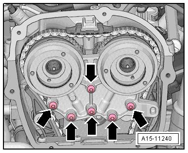
– Apply the sealant on the clean sealing surface of the cylinder head cover as illustrated -arrows-.
♦ Sealant bead thickness: 2 to 3 mm.
– Secure the camshaft and place the cylinder head cover with the camshaft on the cylinder head.
– Lightly push on the cylinder head cover by hand and while doing this turn the camshaft slightly until the cylinder head cover lays free of tension on the cylinder head. – Replace the cylinder head cover bolts. – Tighten the bolts in several steps, tightening sequence. Refer to ⇒ Fig. ““Cylinder Head Cover Tightening Sequence”“ , page 135 .
Note
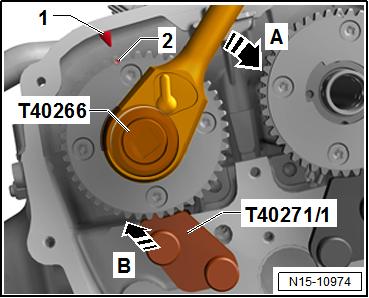

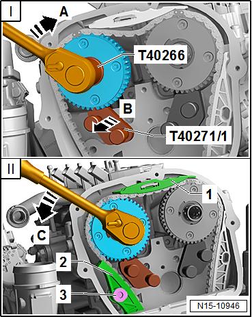
Protected by copyright . Copying fo pivate or commerci al pur po s e s , i n p a r t r o r in w ho le, is not permitted unless authorised by Volkswagen AG. Volkswagen AG does notguarantee or accept any liabilit y wi th res pect t o t h e c o r r e c t n e ss o f in format ion in this document. Copyright by Volkswagen AG. Pay attention that the cylinder head cover is not tilted. – Turn the intake camshaft with the Adapter - T40266- in the direction of the -arrow A- until the markings -1 and 2- align. Push the Camshaft Lock - Component 2 - T40271/2- in the chain sprocket splines in direction of -arrow B-. r – Turn the exhaust camshaft with the Adapter - T40266- in the direction of -arrow A- until the markings -1 and 2- align. Push the Camshaft Lock - Component 1 - T40271/1- in the chain sprocket splines -B-. The mark -2- is offset slightly to the right.

Golf 2015 ➤ , Golf Variant 2015 ➤ Engine Mechanical, Fuel Injection and Ignition - Edition 04.2015
– Turn the crankshaft on the hex fitting to the “TDC point”. In the
“TDC point” flat area -1- is upward.
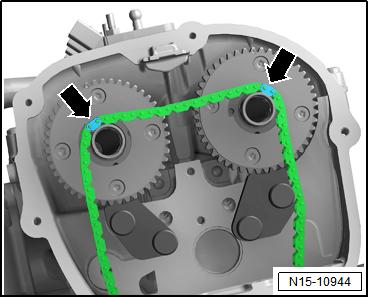
Install Camshaft Timing Chain – Engage the camshaft timing chain with the painted links -arrows- on the camshaft pins.
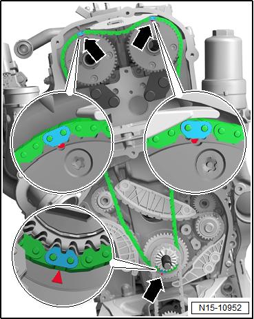
– Place the camshaft timing chain on the intake camshaft, ex‐haust camshaft and the crankshaft. Position the painted chain links -arrows- on the markings on the chain sprockets.

156 Protected by copyright . Copying for pivate or commerci al pur po s e s , i n p a r t r o r in w ho le, is not permitted unless authorised by Volkswagen AG. Volkswagen AG does notguarantee or accept any liabilit y wi th res pect t o t h e c o r r e c t n e ss o f in format ion in this document. Copyright by Volkswagen AG. Rep. Gr.15 - Cylinder Head, Valvetrain
Golf 2015 ➤ , Golf Variant 2015 ➤ Engine Mechanical, Fuel Injection and Ignition - Edition 04.2015
– Install the guide rail -2- and tighten the bolts -1-.

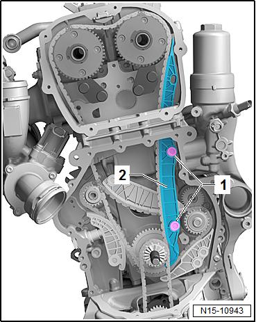
Protected by copyright . Copying fo pivate or commerci al pur po s e s , i n p a r t r o r in w ho le, is not permitted unless authorised by Volkswagen AG. Volkswagen AG does notguarantee or accept any liabilit y wi th res pect t o t h e c o r r e c t n e ss o f in format ion in this document. Copyright by Volkswagen AG. – Install the upper glide rail -1-. r For the following steps a second technician is necessity. I - Turn the exhaust camshaft with the Adapter - T40266- slightly in the direction of -arrow A- and push the Camshaft Lock - Com‐ponent 1 - T40271/1- from the camshaft splines in the direction of -arrow B-. II - Release the camshaft in the direction of -arrow C-, until the timing chain touches the glide rail -1-. Hold the camshaft in this position, install the tensioning rail -2- and tighten the bolts -3-. Release the camshaft.
Golf 2015 ➤ , Golf Variant 2015 ➤ Engine Mechanical, Fuel Injection and Ignition - Edition 04.2015
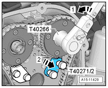
– Turn the intake camshaft with the Adapter - T40266- in the direction of -arrow 1- until the Camshaft Lock - Component 2 - T40271/2- can be pushed out of the chain sprocket splines in the direction of -arrow 2-. Release the camshaft.
– Remove the Camshaft Lock - Component 1 - T40271/1- and Protected by copyright . Copying for piva e or commerci al pur po s e s , i n p a r t r o r in w ho le, is not permitted unless authorised by Volkswagen AG. Volkswagen AG does notguarantee or accept any liabilit y wi th res pect t o t h e c o r r e c t n e ss o f in format ion in this document. Copyright by Volkswagen AG. Camshaft Lock - Component 2 - T40271/2- . – Install the bolts -arrows- and tighten them. Tightening specifi‐cation. Refer to -item 4- ⇒ Item 4 (page 91) . t – Attach the bearing mount. Do not tilt it when doing this. Handtighten the bolts -arrows-.

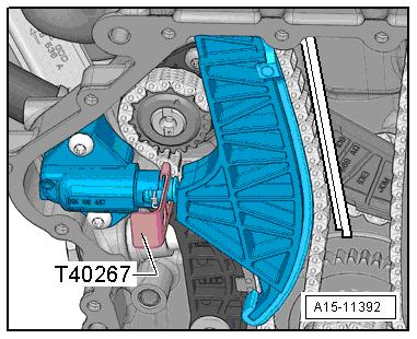
– Remove the Tensioner Locking Tool - T40267- .
Golf 2015 ➤ , Golf Variant 2015 ➤ Engine Mechanical, Fuel Injection and Ignition - Edition 04.2015 Protectd by copyright . Copying for pivate or commerci al pur po e s , i n p a r t r o r in w ho le, is not permitted unless authorised by Volkswagen AG. Volkswagen AG does notguarantee or accept any liabilit y wi th res pect t o t h e c o r r e c t n e ss o f in format ion in this document. Copyright by Volkswagen AG. – Tighten the bearing bracket bolts -arrows-. Tightening speci‐fication. Refer to ⇒ “3.1 Overview - Camshaft Timing Chain”, page 114 . s – Install the chain tensioner -2-. The wire clip must come in to contact with the oil pan upper section opening -arrow-. Tighten the bolt -1- and remove the Locking Pin (3 pc.) - T40011- . e – Check the adjustment. The painted chain links -arrows- must line up with the markings on the chain sprockets. – Install the pilot valves -item 6- ⇒ Item 7 (page 115) . – Let the engine turn a second time in the direction of engine rotation. Note

Due to the ratio, the painted chain links no longer match up after the engine has been turned.

– Remove the Assembly Tool - Knurled Nut - T10531/4- and re‐move the Assembly Tool - Turning Over Tool - T10531/3- . – Install the lower timing chain cover. Refer to ⇒ page 109 .
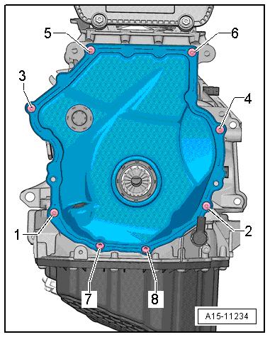
Protected by copyright . Copying fo pivate or commerci al p r po s e s , i n p a r t r o r in w ho le, is not permitted unless authorised by Volkswagen AG. Volkswagen AG does notguarantee or accept any liabilit y wi th res pect t o t h e c o r r e c t n e ss o f in format ion in this document. Copyright by Volkswagen AG. Note Tighten the bolts -1 and 4- with an additional turn after installing the vibration damper. The bolts must be removed again to install the vibration damper. u – Install the vibration damper. Refer to ⇒ “1.4 Vibration Damper, Removing and Installing”, page 47 . – Install the upper timing chain cover. Refer to ⇒ “2.2.1 Upper Timing Chain Cover, Removing and Installing”, page 106 . – Install the ribbed belt tensioning damper. Refer to ⇒ “1.3 Ribbed Belt Tensioner, Removing and Installing”, page 47 . r – Install the ribbed belt. Refer to ⇒ “1.2 Ribbed Belt, Removing and Installing”, page 46 . – Install the vacuum pump. Refer to ⇒ “1.4 Vacuum Pump, Removing and Installing”, page 100 . – Install the high pressure pump. Refer to ⇒ “7.2 High Pressure Pump, Removing and Installing”, page 328 . The rest of the installation is performed in reverse order of re‐moval, noting the following: Golf 2015 ➤ , Golf Variant 2015 ➤ Engine Mechanical, Fuel Injection and Ignition - Edition 04.2015 – After performing work on the chain drive the adaptation value in the Engine Control Module (ECM) must be adapted. To do this turn on the ignition and select the following menu items on the Vehicle Diagnostic Tester :
♦ 01 - Engine Electronics
♦ Guided Functions
♦ 01 - Adaptation After Repair Work on the Chain
Drive
Tightening Specifications ♦ Refer to ⇒ “3.1 Overview - Camshaft Timing Chain”, page 114 . ♦ Refer to ⇒ “3.2 Overview - Balance Shaft Drive Chain”, page 116 . ♦ Refer to ⇒ “4.1 Overview - Valvetrain”, page 133 . ♦ Refer to ⇒ “3.1 Overview - Air Filter Housing”, page 293 . ♦ Refer to ⇒ “7.1 Overview - High Pressure Pump”, page 325 . ♦ Refer to ⇒ Body Exterior; Rep. Gr. 66 ; Noise Insulation;
Overview - Noise Insulation .
Caution
Golf 2015 ➤ , Golf Variant 2015 ➤ Engine Mechanical, Fuel Injection and Ignition - Edition 04.2015
Mandatory Replacement Parts ♦ Bolts - Camshaft Adjustment Valve 1 ♦ O-ring - Camshaft Adjustment Valve 1 ♦ Seal - Camshaft Adjustment Valve 1
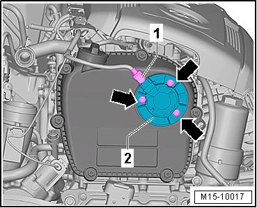
Removing – Remove the engine cover. Refer to ⇒ “3.1 Engine Cover, Removing and Installing”, page 38 . – Unclip the coolant and fuel lines and set them aside. Protectd by copyrigh . Copying fo pivate or commerci al pur po s e s , i n p a r t r o r in w ho le, is not permitted unless authorised by Volkswagen AG. Volkswagen AG does notguarantee or accept any liabilit y wi th res pect t o t h e c o r r e c t n e ss o f in format ion in this document. Copyright by Volkswagen AG. – Disconnect the connector -1- from the Camshaft Adjustment Valve 1 - N205- . – Remove the bolts -arrows- and then the Camshaft Adjustment Valve 1 - N205- -2-. Installing Install in reverse order of removal. Note the following: Note Replace seals and O-rings. – Lubricate seals on the Camshaft Adjustment Valve 1 - N205- / Exhaust Camshaft Adjustment Valve 1 - N318- sealing surfa‐ces with engine oil. Tightening Specifications ♦ Refer to ⇒ “2.1 Overview - Timing Chain Cover”, page 104 . r 4.4 Camshaft Adjustment Valve 1 - N205and Exhaust Camshaft Adjustment Valve 1 - N318- , Removing and Instal‐ling t Caution e This procedure contains mandatory replaceable parts. Refer to component overview prior to starting procedure.
Mandatory Replacement Parts ♦ Bolts - Camshaft Adjustment Valve 1 ♦ O-ring - Camshaft Adjustment Valve 1 ♦ Seal - Camshaft Adjustment Valve 1 ♦ Bolts - Exhaust Camshaft Adjustment Valve 1 ♦ O-ring - Exhaust Camshaft Adjustment Valve 1 ♦ Seal - Exhaust Adjustment Valve 1 Removing – Remove connector -1- from Exhaust Camshaft Adjustment
Valve 1 - N318- and connector -3- from Camshaft Adjustment
Valve 1 - N205- .


