3 minute read
3 Special Tools


Golf 2015 ➤ , Golf Variant 2015 ➤ Engine Mechanical, Fuel Injection and Ignition - Edition 04.2015
1.3 Charge Pressure Actuator - V465- , Ad‐justing
Special tools and workshop equipment required ♦ Mini Torque Wrench - VAS6854♦ Vehicle Diagnostic Tester Removing
Note
Ignore item -4-.
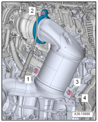
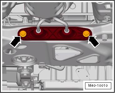
– Remove the bolt -2- and the screw-type clamp. Protectd by copyright . opying for pi ate or co mer i al pur po s e s , i n p a r t r o r in w ho le, is not permitted unless authorised by Volkswagen AG. Volkswagen AG does notguarantee or accept any liabilit y wi th res pect t o t h e c o r r e c t n e ss o f in format ion in this document. Copyright by Volkswagen AG. – Remove the noise insulation. Refer to ⇒ Body Exterior; Rep. Gr. 66 ; Noise Insulation; Overview - Noise Insulation . – Remove the nuts -1 and 3-. c – Remove bolts -arrows- and set the catalytic converter slightly aside. m– Turn on the ignition and select the following menu items on the Vehicle Diagnostic Tester : v♦ 01 - Engine Electronics ♦ Guided Functions C♦ 01 - Charge Pressure Actuator V465 Adjusting e – Adjust the charge pressure actuator linkage to the instructions in the Vehicle Diagnostic Tester . – Tighten the lock nut with the Mini Torque Wrench - VAS6854- . Tightening Specifications ♦ Refer to ⇒ “1.1 Overview - Turbocharger”, page 256 .
Golf 2015 ➤ , Golf Variant 2015 ➤ Engine Mechanical, Fuel Injection and Ignition - Edition 04.2015
2 Charge Air System
⇒ “2.1 Overview - Charge Air System”, page 264 . ⇒ “2.2 Overview - Charge Air Hose Connections”, page 265 . ⇒ “2.3 Charge Air Cooler, Removing and Installing”, page 265 . ⇒ “2.4 Charge Air Pressure Sensor G31 , Removing and Instal‐ling”, page 269 . ⇒ “2.5 Charge Air System, Checking for Leaks”, page 269 . 2.1 Overview - Charge Air System
Note
♦ Assembly of screw-type clamps for the charge air hose connections. Refer to ⇒ “2.2 Overview - Charge Air Hose Connections”, page 265 . ♦ Before testing or performing a repair, check all air guide pipes and hoses and all vacuum lines for leaks and secure seating. ♦ Follow the guidelines for clean working conditions. Refer to ⇒ “3.1 Clean Working Conditions”, page 5 .
1 - Air Guide Pipe 2 - Grommet
3 - Spacer Sleeve 4 - Bolt ❑ 7 Nm
5 - Air Guide Hose ❑ Installing. Refer to ⇒ “2.2 Overview Charge Air Hose Con‐nections”, page 265 . 6 - Air Guide
7 - Charge Air Cooler ❑ Removing and instal‐ling. Refer to ⇒ “2.3 Charge Air Cool‐er, Removing and In‐stalling”, page 265 . 8 - Air Guide

9 - Rubber Bushing ❑ For the charge air cooler 10 - Rubber Bushing ❑ For the charge air cooler 11 - Bolt ❑ 7 Nm
12 - Spacer Sleeve 13 - Grommet
14 - Bolt ❑ 5 Nm
Protected by copyright . Copying for pivate or commerci al pur po s e s , i n p a r t r o r in w ho le, is not permitted unless authorised by Volkswagen AG. Volkswagen AG does notguarantee or accept any liabilit y wi th res pect t o t h e c o r r e c t n e ss o f in format ion in this document. Copyright by Volkswagen AG.


