9 minute read
m2.2 Timing Chain Cover, Removing and Installing


Golf 2015 ➤ , Golf Variant 2015 ➤ Engine Mechanical, Fuel Injection and Ignition - Edition 04.2015
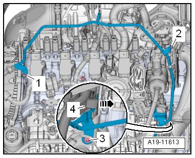
– Disconnect the connector -3- for Knock Sensor 1 - G61- from the bracket.
– Disconnect the connectors -2 through 4-.

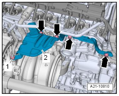
Protected by copyright . Copying for pivate or commer i al pur po s e s , i n p a r t r o r in w ho le, is not permitted unless authorised by Volkswagen AG. Volkswagen AG does notguarantee or accept any liabilit y wi th res pect t o t h e c o r r e c t n e ss o f in format ion in this document. Copyright by Volkswagen AG. – Disconnect the connectors and free up the wires. 1 - For Intake Manifold Runner Control Valve - N3162 - For Coolant Shut-Off Valve - N823 - For Engine Coolant Temperature Sensor - G624 - For Oil Pressure Switch, Level 3 - F447– Remove the bolts -arrows-. c – Remove the bolts -arrows- and nut -1-. – Remove the heat shield -2-.

– Remove the bolt -1-. Just loosen bolt -3-.
– Remove the turbocharger bracket -2-.

Golf 2015 ➤ , Golf Variant 2015 ➤ Engine Mechanical, Fuel Injection and Ignition - Edition 04.2015
– Remove the nuts -arrows-.
– Remove the turbocharger from the cylinder head and tie up behind.
– Remove the bolts -arrows-.
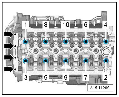
– Remove the cylinder head bolts in the sequence -1 to 10-.
Note

Protected by copyriht . Copying for pivate or co merci al pur po s e s , i n p a r t r o r in w ho le, is not permitted unless authorised by Volkswagen AG. Volkswagen AG does notguarantee or accept any liabilit y wi th res pect t o t h e c o r r e c t n e ss o f in format ion in this document. Copyright by Volkswagen AG. Make sure all wires and cables are disconnected. – Remove the cylinder head and place it on a soft surface (foam). Installing Note m ♦ Replace the bolts that were tightened with an additional turn. ♦ Replace the gaskets, seals and self-locking nuts. ♦ The hose supports, air guide pipes and hoses must be free of oil and grease before installing. ♦ Secure hose connections with standard production clamps. Refer to the Parts Catalog. ♦ The screws on the used clamps must be sprayed with a rust remover before installing. g – Only unpack new cylinder head gasket immediately prior to installation. The silicon layer and the cylinder head seal re‐cessed area must not be damaged. – Carefully remove sealant residue from cylinder head and cyl‐inder block. Make sure that no long scrapes or scratches result. Carefully remove all grinding and sanding residue. – Clean the cylinder head bolt blind holes. If necessary with compressed air. – Set cylinder head gasket in place.
Golf 2015 ➤ , Golf Variant 2015 ➤ Engine Mechanical, Fuel Injection and Ignition - Edition 04.2015
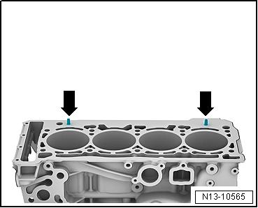
♦ Pay attention to centering pins in cylinder block -arrows-. ♦ Cylinder head gasket installed position: the part number must be readable from the intake side.
– If the crankshaft was turned in the meanwhile: bring the piston for cylinder 1 to Top Dead Center (TDC) and then turn the crankshaft back just a little. Take care not to damage the timing chain in the process. – Set cylinder head in place. – Install and tighten the cylinder head bolt. Tightening se‐quence. Refer to ⇒ Fig. ““Cylinder Head Tightening Sequence”“ , page 92 – Install the camshaft but the camshaft timing chain is not in‐stalled yet. Refer to ⇒ “4.2 Camshaft, Removing and Installing”, page 136 . – Support the engine in its installed position again. Refer to ⇒ “2.5 Engine, Supporting in Installed Position”, page 33 . – Remove the engine mount and the engine support. Refer to ⇒ “1.6 Engine Support, Removing and Installing”, page 55 . – Now install the camshaft timing chain. Refer to ⇒ “4.2 Camshaft, Removing and Installing”, page 136 . Further assembly is performed in the reverse order of removal, thereby observing the following: – Replace the engine oil. Refer to ⇒ Maintenance ; Booklet 36.1 ; Procedure Descriptions; Engine Oil, Draining, Replacing
Oil Filter, and Filling . – Fill with new coolant. Refer to ⇒ “1.3 Coolant, Draining and Filling”, page 217 . Tightening Specifications ♦ Refer to ⇒ “1.1 Overview - Cylinder Head”, page 90 . r ♦ Refer to ⇒ “4.1 Overview - Intake Manifold”, page 296 . ♦ Refer to ⇒ “3.1 Overview - Coolant Pipes”, page 241 . ♦ Refer to ⇒ “1.1 Overview - Turbocharger”, page 256 . ♦ Refer to ⇒ “1.1 Overview - Muffler”, page 338 .
Protected by copyright . Copying fo pivate or commerci al pur po s e s , i n p a r t r o r in w ho le, is not permitted unless authorised by Volkswagen AG. Volkswagen AG does notguarantee or accept any liabilit y wi th res pect t o t h e c o r r e c t n e ss o f in format ion in this document. Copyright by Volkswagen AG.
1.4 Vacuum Pump, Removing and Installing
Caution
This procedure contains mandatory replaceable parts. Refer to component overview prior to starting procedure.
Mandatory Replacement Parts ♦ Seal - Vacuum Pump Removing – Remove the engine cover. Refer to ⇒ “3.1 Engine Cover, Removing and Installing”, page 38 . – Remove the air filter housing. Refer to ⇒ “3.2 Air Filter Housing, Removing and Installing”, page 294 .
Golf 2015 ➤ , Golf Variant 2015 ➤ Engine Mechanical, Fuel Injection and Ignition - Edition 04.2015
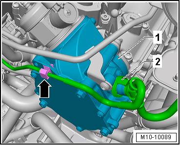
– Unclip the vacuum line -2- from the bracket -arrow-. – Disconnect the vacuum hose -2-.
– Remove the bolts -1, 2 and 3- and carefully move the coolant line slightly to the side.


NOTICE
Protected by copyright . Copying fo pivate or commerci al pur po s e s , i
p a r t o r in w ho le, is not permitted unless authorised by Volkswagen AG. Volkswagen AG does notguarantee or accept any liabilit y wi th res pect t o t h e c o r r e c t n e ss o f Risk of destroying the coolant pipes through deformation. – Never change the coolant pipe bent shape. – Remove the high pressure pump with the roller tappet. Refer to ⇒ “7.2 High Pressure Pump, Removing and Installing”, page 328 . – Remove the bolts -arrows- and remove the vacuum pump. Note n Do not disassemble the vacuum pump. r r Installing – Clean the sealing surfaces. – Turn the vacuum pump coupling plate so that it engages in the camshaft groove when installing the vacuum pump. – Position the new seal on the vacuum pump and insert the two bolts. Position the vacuum pump with the seal on the cylinder head. in format ion in this document. Copyright by Volkswagen AG. – While doing so pay attention that it lays flush on the flange. Further assembly is performed the reverse order of the removal. Tightening Specifications ♦ Refer to ⇒ Fig. ““Vacuum Pump - Tightening Specifications”“ , page 94
1.5 Compression Pressure, Checking
Special tools and workshop equipment required ♦ Spark Plug Removal Tool - 3122B-
Golf 2015 ➤ , Golf Variant 2015 ➤ Engine Mechanical, Fuel Injection and Ignition - Edition 04.2015

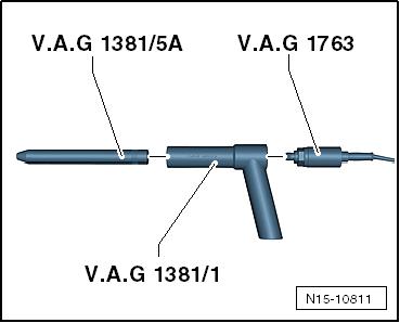
♦ Compression Tester Kit - VAG1763♦ Compression Tester Kit - Adapter 1 - VAG1381/1Protected by copyright . Copying for pivate or co merci al pur po e s , i n p a r t r o r in w ho le, is not permitted unless authorised by Volkswagen AG. Volkswagen AG does notguarantee or accept any liabilit y wi th res pect t o t h e c o r r e c t n e ss o f in format ion in this document. Copyright by Volkswagen AG. ♦ Compression Tester Kit - Adapter 5A - VAG1381/5ATest Sequence Note ♦ Engine oil temperature: minimum 30 °C (86 °F) ♦ Battery voltage at least 12.7 V s – Remove the engine cover. Refer to ⇒ “3.1 Engine Cover, Removing and Installing”, page 38 . – Disconnect the ignition coil sensors connectors and remove them from the ignition coils at the same time. – Remove the ignition coil bolts and remove the ignition coils. – Disconnect the connectors: m 1 - For Fuel Injector -N30- to -N332 - For Cylinder 1 Fuel Injector 2 - N532- to Cylinder 4 Fuel Injector 2 - N535– Remove spark plugs with Spark Plug Removal Tool - 3122B- .
Golf 2015 ➤ , Golf Variant 2015 ➤ Engine Mechanical, Fuel Injection and Ignition - Edition 04.2015
– Check the compression pressure using the Compression
Tester Kit - VAG1763- , Compression Tester Kit - Adapter 1 -
VAG1381/1- and Compression Tester Kit - Adapter 5A -
VAG1381/5A- .
Note
For information on using the tester. Refer to the Operating In‐structions.
– Operate the starter until the tester no longer indicates that the pressure is increasing.
Compression Pressure Pressure
New 11.0 to 14.0 bar (159.54 to 203.05 psi)
Wear limit 7.0 bar (101.52 psi) Protected by copyright . Copying for pivate or commerci al pur po s e s , i n p a r t r o r in w ho le, is not permitted unless authorised by Volkswagen AG. Volkswagen AG does notguarantee or accept any liabilit y wi th res pect t o t h e c o r r e c t n e ss o f in format ion in this document. Copyright by Volkswagen AG. Maximum difference between cylinders 3.0 bar (43.5 psi) – Install the spark plugs. Refer to ⇒ Maintenance ; Booklet 36.1 ; Procedure Descriptions; Spark Plugs, Replacing . – Install the ignition coils. Refer to ⇒ “1.3 Ignition Coils with Power Output Stages, Removing and Installing”, page 357 . Note By separating the connections, Diagnostic Trouble Code (DTCs) are stored to memory. After the test, check and erase the DTC memory. – Turn on the ignition and select the following menu items on the Vehicle Diagnostic Tester : ♦ 01 - Engine Electronics ♦ Guided Functions ♦ 01 - Generate Readiness Code


