7 minute read
4.2 Balance Shaft, Removing and Installing


Protected by copyright . Copying fo pivate or commerci al pur po s s , i n p a r t r o r in w ho le, is not permitted unless authorised by Volkswagen AG. Volkswagen AG does notguarantee or accept any liabilit y wi th res pect t o t h e c o r r e c t n e ss o f in format ion in this document. Copyright by Volkswagen AG. 3 Crankshaft ⇒ “3.1 Overview - Crankshaft”, page 62 ⇒ “3.2 Crankshaft Dimensions”, page 64 ⇒ “3.3 Main Bearing Shells Allocation”, page 64 ⇒ “3.4 Crankshaft Needle Bearing, Replacing”, page 65 ⇒ “3.5 Crankshaft, Measuring Axial Clearance”, page 67 ⇒ “3.6 Crankshaft, Measuring Radial Clearance”, page 67 ⇒ “3.7 Sensor Wheel, Removing and Installing”, page 68 e 3.1 Overview - Crankshaft Note r Secure the engine to the assembly stand using the Engine and Gearbox Bracket - VAS6095A- when performing the assembly work. Refer to ⇒ “1.3 Engine, Securing on Engine and Transmission Holder”, page 23 . 1 - Cylinder Block 2 - Bearing Shell for Cylinder Block ❑ With lubricating groove ❑ Lubricate ❑ Do not interchange used bearing shells (mark) ❑ Crankshaft bearing shells identification (classification). Refer to ⇒ “3.3 Main Bearing Shells Allocation”, page 64 . 3 - Crankshaft ❑ After removal, lay aside so that sensor wheel -item 8⇒ Item 8 (page 63) is not rested on and be‐comes damaged ❑ If the crankshaft is being replaced, then the bear‐ing shells must be allo‐cated to the bearing cover. Refer to ⇒ “3.3 Main Bearing Shells Allocation”, page 64 . ❑ Axial clearance. Refer to ⇒ “3.5 Crankshaft, Measuring Axial Clear‐ance”, page 67 . ❑ Radial clearance. Refer to Golf 2015 ➤ , Golf Variant 2015 ➤ Engine Mechanical, Fuel Injection and Ignition - Edition 04.2015
Golf 2015 ➤ , Golf Variant 2015 ➤ Engine Mechanical, Fuel Injection and Ignition - Edition 04.2015
⇒ “3.6 Crankshaft, Measuring Radial Clearance”, page 67 . ❑ Do not turn crankshaft when measuring radial play ❑ Crankshaft dimensions. Refer to ⇒ “3.2 Crankshaft Dimensions”, page 64 . Protected by copyright . Copying fo pivate or commerci al pur po s e s , i n p a r t r o r in w ho le, is not permitted unless authorised by Volkswagen AG. Volkswagen AG does notguarantee or accept any liabilit y wi th res pect t o t h e c o r r e c t n e ss o f in format ion in this document. Copyright by Volkswagen AG. r 4 - Bearing Shell for Bearing Cap ❑ Without lubricating groove ❑ Lubricate ❑ Do not interchange used bearing shells (mark) ❑ Crankshaft bearing shells identification (classification). Refer to ⇒ “3.3 Main Bearing Shells Allocation”, page 64 . 5 - Bolt ❑ Replace after removing ❑ Tightening sequence. Refer to ⇒ Fig. ““Crankshaft, Tightening Sequence”“ , page 63 6 - Bearing Cap ❑ Bearing cap 1: belt pulley side ❑ Retaining tabs of bearing shells and cylinder block/bearing caps must lie above one another 7 - Bolt ❑ 10 Nm + 90° ❑ Replace after removing ❑ Replace sensor wheel every time bolts are loosened. Refer to ⇒ “3.7 Sensor Wheel, Removing and Installing”, page 68 . 8 - Sensor Wheel ❑ For Engine Speed Sensor - G28❑ It is possible to install in one position only, the holes are offset. ❑ Replace sensor wheel every time bolts are loosened ❑ Removing and installing. Refer to ⇒ “3.7 Sensor Wheel, Removing and Installing”, page 68 . 9 - Thrust Washers ❑ For bearing 3 ❑ Lubricate
10 - Bolt ❑ Replace after removing ❑ Tightening sequence. Refer to ⇒ Fig. ““Crankshaft, Tightening Sequence”“ , page 63
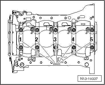
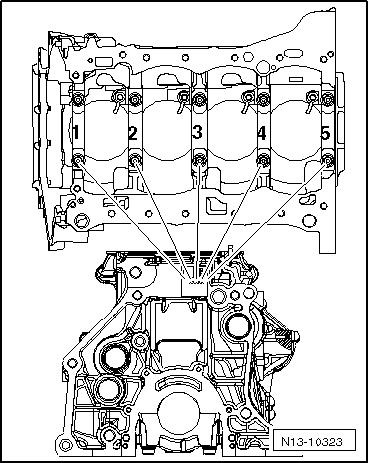
Crankshaft, Tightening Sequence – Tighten the crankshaft bolts in the sequence -1 to 10- and -arrow A- as follows.
Step Bolts Tightening Specification/Addi‐tional Turn
1. -1- through -10- and -arrows AInstall hand-tight
2. -1- through -10- 65 Nm 3. -1- through -10- Turn an additional 90° 4. -A arrows- 20 Nm 5. -A arrows- Turn an additional 90°

Golf 2015 ➤ , Golf Variant 2015 ➤ Engine Mechanical, Fuel Injection and Ignition - Edition 04.2015
Protected by copyright . Copyi g for pivate or co merci al pur po s e s , i n p a r t r o r in w ho le, is not permitted unless authorised by Volkswagen AG. Volkswagen AG does notguarantee or accept any liabilit y wi th res pect t o t h e c o r r e c t n e ss o f in format ion in this document. Copyright by Volkswagen AG. 3.2 Crankshaft Dimensions (Dimensions in mm) Reconditioning Dimension 1)
Crankshaft Bearing Pin Diameter
Connecting Rod Bearing Pin Diame‐ter Basic dimension 58.00 47.80 1) The preparation of worn crankshafts is not provided. 3.3 Main Bearing Shells Allocation The bearing shells are allocated to the cylinder block with the correct thickness at the factory. Colored spots serve to identify the bearing thicknesses. The code letters on the lower contact surface or on the top of the cylinder block identify which bearing shell and where it must be mounted on the cylinder block (upper bearing shell). The code letters on the crankshaft identify which bearing shells m and where they must be installed in the bearing cover (lower bearing shell). The first letter is for bearing cover one, the second for bearing cover two, etc. n Cylinder Block Bearing Shell Identification: Note The cylinder block identification may be located either on the oil pan sealing surface or on the top (transmission side) of the cyl‐inder block.
The identification on the cylinder block is for the upper bearing shell.
– Write down the letters and then use the table to find the color identification.
Golf 2015 ➤ , Golf Variant 2015 ➤ Engine Mechanical, Fuel Injection and Ignition - Edition 04.2015
Bearing Cap Bearing Shell Identification: The identification on the crankshaft is for the lower bearing shell. – Write down the letters and then use the table to find the color identification.
S = R = G = Black Red Yellow
B =
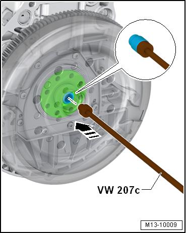
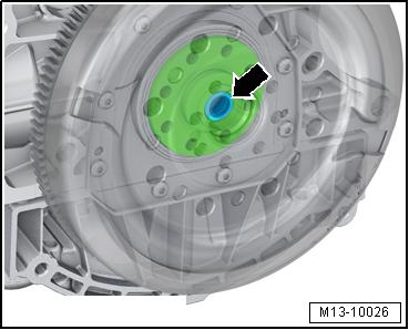
Blue Protected by opyright . Copying fo pivate r comm rci al p r po s s , i n p a r t r o r in w ho le, is not permitted unless authorised by Volkswagen AG. Volkswagen AG does notguarantee or accept any liabilit y wi th res pect t o t h e c o r r e c t n e ss o f in format ion in this document. Copyright by Volkswagen AG. W = White 3.4 Crankshaft Needle Bearing, Replacing e Only for Vehicles Equipped with a Twin Clutch Transmission Special tools and workshop equipment required ♦ Counter-support for example Puller - Kukko Counterstay 22/1u♦ Internal puller, for example Puller - Kukko Internal - 14-19mm - 21/2e♦ Bearing Installer - Bearing Press Piece - VW207Co Caution r This procedure contains mandatory replaceable parts. Refer to component overview prior to starting procedure. cMandatory Replacement Parts ♦ Bearing - Crankshaft Needle Conditions

• Always replace the needle bearing -arrow- after the engine and transmission are separated. • The front edges of the internal puller must not be broken off.

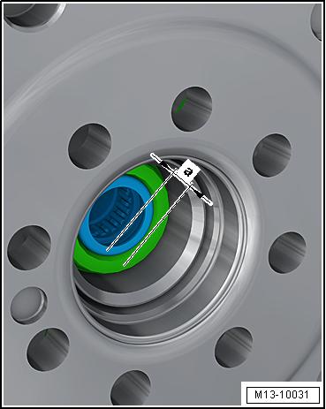
Protected by copyright . Copying fo pivate or commerci al pur po s e s , i n p a r t r o r in w ho le, is not permitted unless authorised by Volkswagen AG. Volkswagen AG does notguarantee or accept any liabilit y wi th res pect t o t h e c o r r e c t n e ss o f in format ion in this document. Copyright by Volkswagen AG. Remove Needle Bearing – Remove the needle bearing -1- from the crankshaft -2- using a standard internal puller such as the Puller - Kukko Internal 14-19mm - 21/2- and counter support Puller - Kukko Counter‐stay - 22/1- . – The internal puller must be positioned behind the needle ring -arrow-. r Installing – Clean the bearing seat in the crankshaft and thinly coat with grease. – Drive the needle bearing into the crankshaft up to the instal‐lation depth using the Bearing Installer - Bearing Press Piece - VW207C- . Golf 2015 ➤ , Golf Variant 2015 ➤ Engine Mechanical, Fuel Injection and Ignition - Edition 04.2015 Installation Depth Dimension -a- = 2.0 mm Note
If the needle bearing was unintentionally pushed in too deeply, it must be replaced, because it will be damaged when it is removed again.