4 minute read
2.2 Catalytic Converter, Removing and Installing


Golf 2015 ➤ , Golf Variant 2015 ➤ Engine Mechanical, Fuel Injection and Ignition - Edition 04.2015
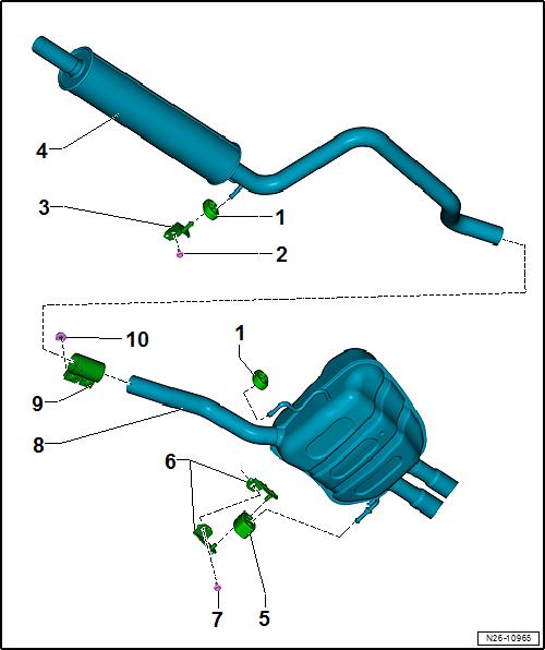
1.1.3 Overview - Muffler, Golf Wagon
1 - Retaining Loop ❑ Replace if damaged 2 - Bolt ❑ 20 Nm
3 - Mount ❑ Replace if damaged 4 - Center Muffler ❑ Original equipment as one unit with rear muf‐fler. For repairs, replace Protected by copyriht . Copying for pivate or co merci al pur po s e s , i n p a r t r o r in w ho le, is not permitted unless authorised by Volkswagen AG. Volkswagen AG does notguarantee or accept any liabilit y wi th res pect t o t h e c o r r e c t n e ss o f in format ion in this document. Copyright by Volkswagen AG. m each separately ❑ Removing and instal‐ling. Refer to ⇒ “1.3 Muffler, Remov‐ing and Installing”, page 343 . ❑ Separating the exhaust pipes/mufflers. Refer to ⇒ “1.2 Exhaust Pipes/ Mufflers, Separating”, page 342 . ❑ Exhaust System, Instal‐ling without Tension. Refer to ⇒ “1.4 Exhaust System, Installing without Ten‐sion”, page 345 . 5 - Retaining Loop ❑ Replace if damaged 6 - Mount ❑ Replace if damaged 7 - Bolt ❑ 20 Nm g 8 - Rear Muffler ❑ Original equipment as one unit with center muffler. For repairs, replace each separately ❑ Removing and installing. Refer to ⇒ “1.3 Muffler, Removing and Installing”, page 343 . ❑ Separating the exhaust pipes/mufflers. Refer to ⇒ “1.2 Exhaust Pipes/Mufflers, Separating”, page 342 . ❑ Exhaust System, Installing without Tension. Refer to ⇒ “1.4 Exhaust System, Installing without Tension”, page 345 . 9 - Rear Clamping Sleeve ❑ Before tightening, align exhaust system free of tension. Refer to ⇒ “1.4 Exhaust System, Installing without Tension”, page 345 . ❑ Installed position. Refer to ⇒ “1.6 Clamping Sleeve Installation Position”, page 347 ❑ Tighten threaded connections evenly. 10 - Nut ❑ 30 Nm
Golf 2015 ➤ , Golf Variant 2015 ➤ Engine Mechanical, Fuel Injection and Ignition - Edition 04.2015
1.2 Exhaust Pipes/Mufflers, Separating
⇒ “1.2.1 Golf”, page 342 ⇒ “1.2.2 Golf Wagon”, page 342 1.2.1 Golf
Special tools and workshop equipment required ♦ Chain Pipe Cutter - VAS6254Protected by copyright . Copying fo pivate or commerci al pur po s e s , i n p a r t r o r in w ho le, is not permitted unless authorised by Volkswagen AG. Volkswagen AG does notguarantee or accept any liabilit y wi th res pect t o t h e c o r r e c t n e ss o f in format ion in this document. Copyright by Volkswagen AG. ♦ Pneumatic Body Saw - VAS6780♦ A separating point has been provided in the connecting pipe for individual replacement of the center or rear muffler. ♦ The separating point is marked by a depression around the circumference of the exhaust pipe. Procedure – Disconnect the exhaust pipe at the separating point -arrow- at a right angle using the Chain Pipe Cutter - VAS6254- or Pneu‐matic Body Saw - VAS6780- . r – When installing position the clamping sleeve -arrow- at the side markings. – Note the installation position. Refer to ⇒ “1.6 Clamping Sleeve Installation Position”, page 347 . – Install the exhaust system free of tension. Refer to ⇒ “1.4 Exhaust System, Installing without Tension”, page 345 .
1.2.2 Golf Wagon
Special tools and workshop equipment required ♦ Chain Pipe Cutter - VAS6254♦ A separating point has been provided in the connecting pipe for individual replacement of the center or rear muffler. ♦ The separating point is marked by a depression around the circumference of the exhaust pipe.
Golf 2015 ➤ , Golf Variant 2015 ➤ Engine Mechanical, Fuel Injection and Ignition - Edition 04.2015
Procedure
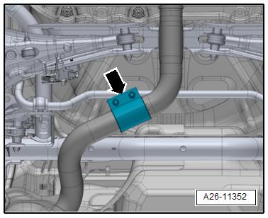
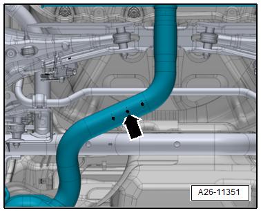
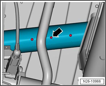
– Separate the exhaust pipe at a right angle at the separating point -arrow- using a Chain Pipe Cutter - VAS6254- .
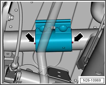
– When installing, position the clamping sleeve central to the side markings -arrows-. – Install the rear clamping sleeve. Refer to ⇒ “1.6 Clamping Sleeve Installation Position”, page 347 . – Install the exhaust system free of tension. Refer to ⇒ “1.4 Exhaust System, Installing without Tension”, page 345 . e
Proteced by copyright . Copying for piva e or commerci al pur po s s , i n p a r t r o r in w ho le, is not permitted unless authorised by Volkswagen AG. Volkswagen AG does notguarantee or accept any liabilit y wi th res pect t o t h e c o r r e c t n e ss o f in format ion in this document. Copyright by Volkswagen AG. t 1.3 Muffler, Removing and Installing ⇒ “1.3.1 Golf”, page 343 ⇒ “1.3.2 Golf Wagon”, page 344 1.3.1 Golf tRemoving – If equipped, remove the left rear underbody panel. Refer to ⇒
Body Exterior; Rep. Gr. 66 ; Underbody Panel; Overview -
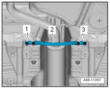
Underbody Panels . – Remove the rear tunnel brace -2-. Refer to ⇒ Body Exterior;
Rep. Gr. 66 ; Underbody Panel; Overview - Underbody Pan‐els .