6 minute read
5.3 Pistons and Cylinder Bore, Checking


Golf 2015 ➤ , Golf Variant 2015 ➤ Engine Mechanical, Fuel Injection and Ignition - Edition 04.2015
– Lubricate the balance shaft mountings -arrows- with engine oil.
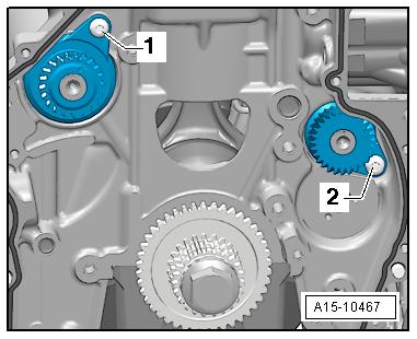
– Install the intake side balance shaft and tighten the bolt -2-.
– Replace the O-ring -1- and coat with engine oil. – Coat the mounting pin with engine oil and insert it. The align‐ment pin -arrow- for the mounting pin must engage in the hole s in the cylinder block.
Note

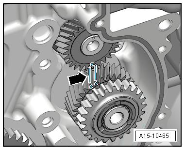
Protectd by copyright . Copying fo pivate or commerci al pur po e s , i n p a r t r o r in w ho le, is not permitted unless authorised by Volkswagen AG. Volkswagen AG does notguarantee or accept any liabilit y wi th res pect t o t h e c o r r e c t n e ss o f in format ion in this document. Copyright by Volkswagen AG. r ♦ Always replace the intermediate sprocket. Otherwise the backlash will not adjust itself and it could result in engine dam‐age. ♦ The new intermediate sprocket has an anti-friction coating that wears off after a short period of use, which automatically ad‐justs the backlash. e – Mark the tooth face on the intermediate sprocket -arrows-. – Install the intermediate sprocket; the marking on the balance shaft must be between the markings on the tooth faces.
Golf 2015 ➤ , Golf Variant 2015 ➤ Engine Mechanical, Fuel Injection and Ignition - Edition 04.2015
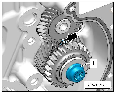
– Tighten the bolt -1- for the intermediate sprocket: tightening sequence. Refer to ⇒ Fig. ““Intermediate Sprocket Tightening Sequence”“ , page 118 . – Check the markings on the intermediate sprocket/balance shaft -arrow-.
Assemble in reverse order of disassembly. Note the following: – Install the balance shaft drive chain. Refer to ⇒ “3.4 Balance Shaft Drive Chain, Removing and Installing”, page 130 . – Install camshaft timing chain. Refer to ⇒ “3.3 Camshaft Timing Chain, Removing and Installing”, page 118 . – Install the lower timing chain cover. Refer to ⇒ “2.2.2 Lower Timing Chain Cover, Removing and Installing”, page 108 . – Install the upper timing chain cover. Refer to ⇒ “2.2.1 Upper Timing Chain Cover, Removing and Installing”, page 106 . – Replace the intake side balance shaft seal. Refer to ⇒ “4.3 Balance Shaft Sealing Ring, Replacing, Intake Side”, page 75 . – Install the toothed belt on the coolant pump. Refer to ⇒ “2.8 Coolant Pump Toothed Belt, Removing and Installing”, page 235 . Tightening Specifications ♦ Refer to ⇒ “4.1 Overview - Balance Shaft”, page 69 .
Protected by copyriht . Copying fo pivate or commerci al p r po s s , i n p a r t r o r in w ho le, is not permitted unless authorised by Volkswagen AG. Volkswagen AG does notguarantee or accept any liabilit y wi th res pect t o t h e c o r r e c t n e ss o f in format ion in this document. Copyright by Volkswagen AG. 4.2.2 Balance Shaft Exhaust Side, Removing and Installing Caution This procedure contains mandatory replaceable parts. Refer to component overview prior to starting procedure. e Mandatory Replacement Parts ♦ Balance Shaft - Exhaust Side u♦ Bearing - Needle Rim ♦ Bolt - Exhaust Side Balance Shaft Note r Balance shaft and needle bearing must be replaced after every removal. Install a new needle bearing with the same color identi‐fication gRemoving • Engine removed. – Remove timing chain upper cover. Refer to ⇒ “2.2.1 Upper Timing Chain Cover, Removing and Installing”, page 106 .
Golf 2015 ➤ , Golf Variant 2015 ➤ Engine Mechanical, Fuel Injection and Ignition - Edition 04.2015
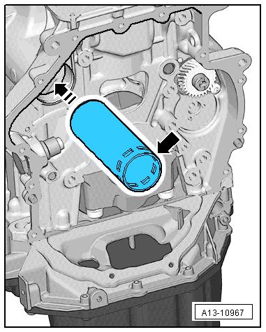
– Remove the lower timing chain cover. Refer to ⇒ “2.2.2 Lower Timing Chain Cover, Removing and Installing”, page 108 . – Remove the camshaft timing chain. Refer to ⇒ “3.3 Camshaft Timing Chain, Removing and Installing”, page 118 . – Remove the balance shaft drive chain. Refer to Protected by copyright . Copying for pivate or commerci al p r po s e s , i n p a r t r o r in w ho le, is not permitted unless authorised by Volkswagen AG. Volkswagen AG does notguarantee or accept any liabilit y wi th res pect t o t h e c o r r e c t n e ss o f in format ion in this document. Copyright by Volkswagen AG. ⇒ “3.4 Balance Shaft Drive Chain, Removing and Installing”, page 130 . – Remove the bolt -1- for the exhaust side balance shaft and remove the balance shaft. u Installing – Check the installed position for the balance shaft pipe. The openings -arrow- must face the chain side.
– Lubricate the balance shaft mountings -arrows- with engine oil.
Golf 2015 ➤ , Golf Variant 2015 ➤ Engine Mechanical, Fuel Injection and Ignition - Edition 04.2015
– Install the exhaust side balance shaft.
– Before tightening the bolt -1- make sure the balance shaft lies level on the crankshaft.
Note Protected by copyriht . Copying fo pivate or co merci al pur po s e s , i n p a r t r o r in w ho le, is not permitted unless authorised by Volkswagen AG. Volkswagen AG does notguarantee or accept any liabilit y wi th res pect t o t h e c o r r e c t n e ss o f in format ion in this document. Copyright by Volkswagen AG. If the balance shaft is not level, then the pipe for the balance shaft must be installed again. m Assemble in reverse order of disassembly. Note the following: – Install the balance shaft drive chain. Refer to ⇒ “3.4 Balance Shaft Drive Chain, Removing and Installing”, page 130 . – Install camshaft timing chain. Refer to ⇒ “3.3 Camshaft Timing Chain, Removing and Installing”, page 118 . – Install the lower timing chain cover. Refer to ⇒ “2.2.2 Lower Timing Chain Cover, Removing and Installing”, page 108 . – Install the upper timing chain cover. Refer to ⇒ “2.2.1 Upper Timing Chain Cover, Removing and Installing”, page 106 . Tightening Specifications ♦ Refer to ⇒ “4.1 Overview - Balance Shaft”, page 69 . r 4.3 Balance Shaft Sealing Ring, Replacing, Intake Side g Special tools and workshop equipment required ♦ Seal Installer, Intermediate Shaft - T10356/1Caution
Mandatory Replacement Parts ♦ Bolt - Sprocket ♦ Seal - Balance Shaft Intake Side
Procedure
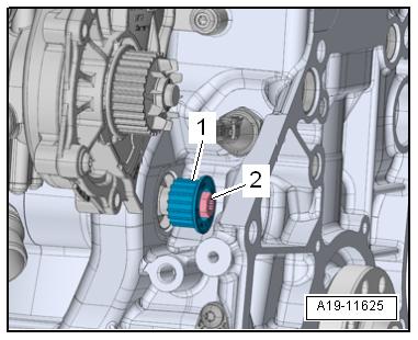
– Remove the toothed belt from the coolant pump. Refer to ⇒ “2.8 Coolant Pump Toothed Belt, Removing and Installing”, page 235 . – Remove the bolt -2-.
– Remove the drive wheel -1- for the toothed belt from the cool‐ant pump. – Firmly press a screwdriver -1- on the seal surface -2- in direc‐tion of -arrow B-.