
5 minute read
4.2 Overview - Intake Manifold Lower Section with Fuel Rail


Golf 2015 ➤ , Golf Variant 2015 ➤ Engine Mechanical, Fuel Injection and Ignition - Edition 04.2015
Note
♦ Fill the ultrasonic device up to the upper edge of the holes with cleaner (see the magnified area of the illustration). ♦ Observe the safety precautions and the operating instructions for the ultrasonic device.
Cleaning – Remove the fuel injectors. Refer to ⇒ “2.2 Fuel Injectors, Removing and Installing”, page 285 . – The ultrasonic device must be filled with cleaning fluid. – Install the combustion chamber fuel injectors -1- all the way into the Mounting Plate for Injection Modules - VAS6418/1-2-.
– Dip the combustion chamber fuel injectors into the cleaner with the Mounting Plate for Injection Modules - VAS6418/1- . – Set the temperature control -4- to 50 °C (122 °F). – Set the time control -5- to 30 minutes.
– Turn on the ultrasonic device -3-.
Note Protected by copyright . Copying for pivate or commerci al pur po s e s , i n p a r t r o r in w ho le, is not permitted unless authorised by Volkswagen AG. Volkswagen AG does notguarantee or accept any liabilit y wi th res pect t o t h e c o r r e c t n e ss o f in format ion in this document. Copyright by Volkswagen AG. The time begins counting down once the cleaning temperature reaches 50 degrees. – Always replace the combustion chamber seal (Teflon seal) af‐ter cleaning each combustion chamber fuel injector. Refer to ⇒ “2.4 Fuel Injector Seals, Replacing”, page 288 . – Install the combustion chamber fuel injectors. Refer to ⇒ “2.2 Fuel Injectors, Removing and Installing”, page 285 .

3 Air Filter
⇒ “3.1 Overview - Air Filter Housing”, page 293 . ⇒ “3.2 Air Filter Housing, Removing and Installing”, page 294 . 3.1 Overview - Air Filter Housing
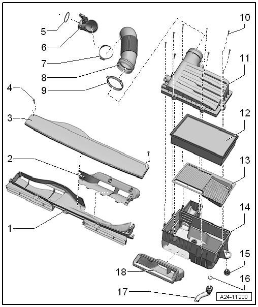
1 - Air Guide- Lower Section ❑ On the lock carrier
2 - Air Guide- Upper Section ❑ On the lock carrier
3 - Cover ❑ For the air guide 4 - Bolt ❑ 2 Nm
5 - Seal
6 - Air Guide Hose
7 - Screw-Type Clamp 8 - Air Guide Hose
9 - Spring Clamp 10 - Bolts ❑ 1.5 Nm
11 - Air Filter Housing Upper Section ❑ Clean off dirt, leaves and salt residue
12 - Air Filter ❑ Use the original-air filter element. Refer to the g Parts Catalog. ❑ For the change inter‐vals. Refer to the ⇒ Maintenance ; Book‐let 36.1 ; Service Work; Service Tables . ❑ Removing and instal‐ling. Refer to ⇒ Mainte‐nance ; Booklet 36.1 ; Procedure Descriptions; Air Filter, Cleaning Housing and Replacing Filter . 13 - Insert ❑ For the air filter lower section
14 - Air Filter Housing Lower Section ❑ Clean off dirt, leaves and salt residue 15 - Rubber Buffer
16 - O-Ring ❑ Replace if damaged 17 - Water Drain Hose ❑ With valve ❑ Clean Golf 2015 ➤ , Golf Variant 2015 ➤ Engine Mechanical, Fuel Injection and Ignition - Edition 04.2015
Protected by copyriht . Copying for pivate or commerci al pur po s e s , i n p a r t r o r in w ho le, is not permitted unless authorised by Volkswagen AG. Volkswagen AG does notguarantee or accept any liabilit y wi th res pect t o t h e c o r r e c t n e ss o f in format ion in this document. Copyright by Volkswagen AG.
Golf 2015 ➤ , Golf Variant 2015 ➤ Engine Mechanical, Fuel Injection and Ignition - Edition 04.2015
18 - Air Guide ❑ On the air filter housing lower section
3.2 Air Filter Housing, Removing and Instal‐ling
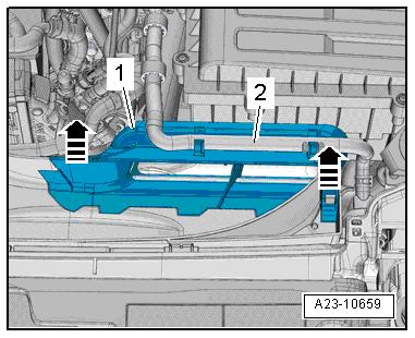
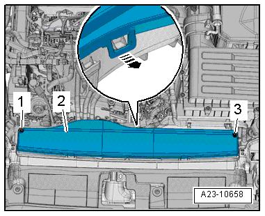
Removing Protected by copyright . Copying for pivate or commerci al p r po s e s , i n p a r t r o r in w ho le, is not permitted unless authorised by Volkswagen AG. Volkswagen AG does notguarantee or accept any liabilit y wi th res pect t o t h e c o r r e c t n e ss o f in format ion in this document. Copyright by Volkswagen AG. – Remove the bolts -1 and 3-. – Open the lock in direction of -arrow- and remove the cover -2-. u – Free up the coolant hose -2-. – Release the locking mechanism in direction of -arrows- and remove the air guide upper section -1-.
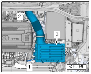
Protected by copyright . Co ying for pivate or co merci al pur po s e s , i n p a r t r o r in w ho le, is not permitted unless authorised by Volkswagen AG. Volkswagen AG does notguarantee or accept any liabilit y wi th res pect t o t h e c o r r e c t n e ss o f in format ion in this document. Copyright by Volkswagen AG. – Disconnect the vacuum hose -1-. – Loosen the clamp -2- and remove the air guide hose. – Carefully remove the air filter housing -3-. Installing Note ♦ Use silicone-free lubricant to mount the air guide hose. ♦ Secure hose connections with standard production clamps. Refer to the Parts Catalog. – Check the air guide hose (clean air side) for salt residue, dirt and leaves. m – Check intake channels up to the air filter insert for dirt. – Install the air filter housing. Note p The water drain hose must be routed straight down and without any bends.
Golf 2015 ➤ , Golf Variant 2015 ➤ Engine Mechanical, Fuel Injection and Ignition - Edition 04.2015


