3 minute read
8.3 Oxygen Sensor 1 after Catalytic Converter GX7 , Removing and Installing


Golf 2015 ➤ , Golf Variant 2015 ➤ Engine Mechanical, Fuel Injection and Ignition - Edition 04.2015
Protected by copyriht . Copying for p vate or co merci al pur po e s , i n p a r t r o r in w ho le, is not permitted unless authorised by Volkswagen AG. Volkswagen AG does notguarantee or accept any liabilit y wi th res pect t o t h e c o r r e c t n e ss o f in format ion in this document. Copyright by Volkswagen AG.
s
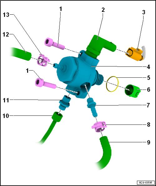
Installing”, page 328 . 4 - O-Ring ❑ Replace if damaged 5 - Roller Tappet ❑ Remains inserted in the vacuum pump after removing the high pressure pump 6 - High Pressure Pump Bolt ❑ 8 Nm + 90° turn ❑ Replace after removing ❑ Tighten by hand 7 - Fuel Supply Line Connection ❑ 30 Nm ❑ Replace after removing ❑ When loosening the high pressure line, secure the connection from turning. 8 - Fuel Supply Line ❑ 27 Nm ❑ For the fuel injector fuel rail ❑ Lubricate the fuel supply line ball with engine oil ❑ Install fuel supply line free of stress 9 - Spring Clamp ❑ Replace if damaged 10 - Fuel Supply Line ❑ Coming from the fuel tank
m 7.1.2 Overview - High Pressure Pump, Vehi‐cles with Intake-Manifold Fuel Injection i CAUTION Fuel system is under high pressure. Risk of injury from fuel spraying out. –g Reducing the fuel high pressure.
Golf 2015 ➤ , Golf Variant 2015 ➤ Engine Mechanical, Fuel Injection and Ignition - Edition 04.2015
1 - High Pressure Pump Bolts ❑ 20 Nm ❑ Replace after removing ❑ Tighten uniformly 2 - Fuel Pressure Regulator Valve - N276-
3 - Connector ❑ For Fuel Pressure Reg‐ulator Valve - N276-
4 - High Pressure Pump ❑ There is an electric fuel Protected by copyright . Copying fo pivate or commerci al pur po s e s , i n p a r t r o r in w ho le, is not permitted unless authorised by Volkswagen AG. Volkswagen AG does notguarantee or accept any liabilit y wi th res pect t o t h e c o r r e c t n e ss o f in format ion in this document. Copyright by Volkswagen AG. r pump located in the fuel tank that supplies the fuel to the mechanical high pressure pump. ❑ When installing, make sure that no dirt enters the fuel system. ❑ The fuel system must be without pressure, re‐leasing fuel pressure. Refer to ⇒ “1.2 High Fuel Pres‐sure, Reducing”, page 283 ❑ Install the fuel lines free of tension ❑ Inspect the O-ring, and replace if damaged ❑ Removing and instal‐ling. Refer to ⇒ “7.2 High Pressure Pump, Removing and Installing”, page 328 . 5 - O-Ring ❑ Replace if damaged 6 - Roller Tappet ❑ Installation position: the roller points to the camshaft ❑ Remains inserted in the vacuum pump after removing the high pressure pump 7 - Fuel Line Connections ❑ 20 Nm
8 - Spring Clamp ❑ Replace after removing 9 - Fuel Line ❑ To the fuel rail intake manifold fuel injectors 10 - High Pressure Line ❑ 20 Nm ❑ To the combustion chamber fuel injectors fuel rail ❑ Lubricate the high pressure line with engine oil ❑ Do not install the high pressure line with tension. Make sure it is clean. 11 - High Pressure Line Connection ❑ 30 Nm ❑ When loosening the high pressure line, secure the connection from turning.


