
3 minute read
4.3 Balance Shaft Sealing Ring, Replacing, Intake Side


Golf 2015 ➤ , Golf Variant 2015 ➤ Engine Mechanical, Fuel Injection and Ignition - Edition 04.2015
3.5 Crankshaft, Measuring Axial Clearance
Special tools and workshop equipment required ♦ Dial Gauge Holder - VW387♦ Dial Gauge - 0-10mm - VAS6079Procedure
– Attach the Dial Gauge - 0-10mm - VAS6079- with the Dial
Gauge Holder - VW387- to the cylinder block and with ap‐proximately 2 mm tension, set indicator against crankshaft counterweight. – Push the crankshaft against the dial gauge by hand and set the dial gauge to “0”. – Remove the crankshaft from the dial gauge and read the measurement.
Axial clearance:
• New: 0.07 to 0.23 mm.
• Wear limit: 0.30 mm.
r po s e s , i d by copyright . Copying fo pivate or commerci al p Protect
p a r t r o r in w ho le, is not permitted unless authorised by Volkswagen AG. Volkswagen AG does notguarantee or accept any liabilit y wi th res pect t o t h e c o r r e c t n e ss o f in format ion in this document. Copyright by Volkswagen AG. n 3.6 Crankshaft, Measuring Radial Clear‐ance u Special tools and workshop equipment required ♦ Plastigage® Procedure Note r♦ Do not interchange used bearings ♦ Bearing shells that are worn down to the nickel layer must be replaced. e– Remove the crankshaft bearing cap and clean the bearing cap and pins. – Place Plastigage® over entire width of bearing journal or into bearing shells. • Plastigage® must rest in center of bearing shell.
Golf 2015 ➤ , Golf Variant 2015 ➤ Engine Mechanical, Fuel Injection and Ignition - Edition 04.2015
– Install the crankshaft bearing and secure with the old bolts -1 to 10-. Refer to ⇒ Fig. ““Crankshaft, Tightening Sequence”“ , page 63 . Do not turn the crankshaft.
Note
Ignore bolts -arrow A-.
– Remove the crankshaft bearing cap again. – Compare width of Plastigage® with calibrated scale. Radial clearance:
• New: 0.017 to 0.037 mm.
• Wear limit: 0.15 mm.

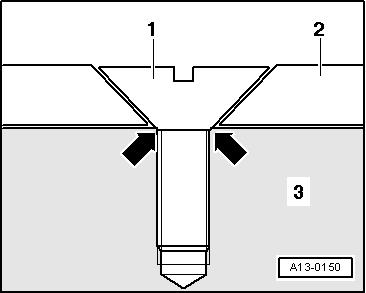
Protected by copyriht . Copying for pivate or comm rci al p r po s e s , i n p a r t r o r in w ho le, is not permitted unless authorised by Volkswagen AG. Volkswagen AG does notguarantee or accept any liabilit y wi th res pect t o t h e c o r r e c t n e ss o f in format ion in this document. Copyright by Volkswagen AG. 3.7 Sensor Wheel, Removing and Installing – Removing engine. Refer to ⇒ “1.1 Engine, Removing”, page 8 . – Remove the sealing flange on the transmission side. Refer to ⇒ “2.3 Sealing Flange, Removing and Installing, Transmission Side”, page 59 . – Remove the oil pan upper section. Refer to ⇒ “1.4 Oil Pan Upper Section, Removing and Installing”, page 185 . u – Remove the balance shaft timing chain. Refer to ⇒ “3.4 Balance Shaft Drive Chain, Removing and Installing”, page 130 – Remove the connecting rod bearing cover. – Remove the crankshaft bearing cover. – Remove the crankshaft and the sensor wheel. e– Replace the sensor wheel -2- each time the bolts -1- are loos‐ened. Note g ♦ After tightening a second time, the attachment point of the countersunk screws of the sensor wheel are so deformed that the screw heads lie on the crankshaft -3- -arrows- and the sensor wheel is loose underneath the screws. ♦ Installation of the sensor wheel is only possible in one position, the bore holes are shifted.
Tightening Specifications ♦ Refer to ⇒ “3.1 Overview - Crankshaft”, page 62 .


