
18 minute read
C3.3 Camshaft Timing Chain, Removing and Installing


Golf 2015 ➤ , Golf Variant 2015 ➤ Engine Mechanical, Fuel Injection and Ignition - Edition 04.2015
– Make sure both alignment bushings for centering the cover -arrows- are present.
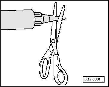
– Cut the tube nozzle at the front marking (nozzle diameter: ap‐proximately 3 mm).
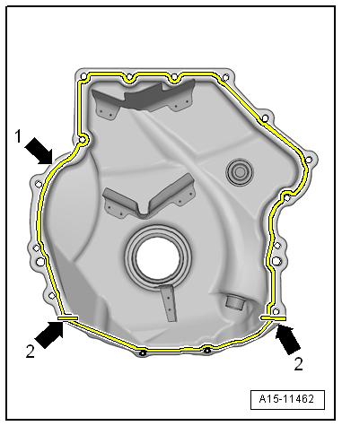
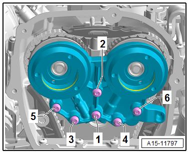
Protected by copyright . Copying for pivate or commerci al pur po s e s , i n p a r t r o r in w ho le, is not permitted unless authorised by Volkswagen AG. Volkswagen AG does notguarantee or accept any liabilit y wi th res pect t o t h e c o r r e c t n e ss o f in format ion in this document. Copyright by Volkswagen AG. Cover with 15 bolts – Apply the Silicone Sealant - D 174 003 A2- to the clean sealing surface -arrow 1- and on the edges -arrows 2- of the new cover as shown in the illustration. ♦ Sealant bead thickness: 2 to 3 mm.
Golf 2015 ➤ , Golf Variant 2015 ➤ Engine Mechanical, Fuel Injection and Ignition - Edition 04.2015
– Immediately attach the cover and tighten the bolts.
Note
– Tighten the bolts -1 through 15- in the sequence shown. Refer to ⇒ “2.1 Overview - Timing Chain Cover”, page 104 .
Cover with 8 Bolts

– Apply the Silicone Sealant - D 174 003 A2- to the clean sealing surface -arrow 1- and on the edges -arrows 2- of the new cover as shown in the illustration.
♦ Sealant bead thickness: 2 to 3 mm.
Note

r po s e s , i
Protected by copyright . Copying for pivate or commerci al p
♦ ♦ p a r t r o r in w ho le, is not permitted unless authorised by Volkswagen AG. Volkswagen AG does notguarantee or accept any liabilit y wi th res pect t o t h e c o r r e c t n e ss o f in format ion in this document. Copyright by Volkswagen AG. n The cover must be installed within five minutes after applica‐tion of silicone sealant. u The sealant bead may not be thicker than specified, otherwise excess sealant could enter the oil pan and clog the oil intake pipe screen.
Golf 2015 ➤ , Golf Variant 2015 ➤ Engine Mechanical, Fuel Injection and Ignition - Edition 04.2015
– Immediately attach the cover and tighten the bolts.
Note
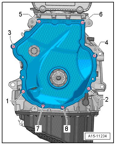
– Tighten the bolts -1 through 8- in the sequence shown. Refer Protected by copyright . Copying fo pivate or commerci al pur po s e s , i n p a r t r o r in w ho le, is not permitted unless authorised by Volkswagen AG. Volkswagen AG does notguarantee or accept any liabilit y wi th res pect t o t h e c o r r e c t n e ss o f in format ion in this document. Copyright by Volkswagen AG. to ⇒ “2.1 Overview - Timing Chain Cover”, page 104 . Continuation for Both Versions r – Install the vibration damper. Refer to ⇒ “1.4 Vibration Damper, Removing and Installing”, page 47 . – Install the Oil Pressure Regulation Valve - N428- . Refer to ⇒ “4.8 Oil Pressure Regulation Valve N428 , Removing and Installing”, page 206 . – Install the ribbed belt tensioning damper. Refer to ⇒ “1.5 Auxiliary Components Bracket, Removing and Instal‐ling”, page 53 . – Install the ribbed belt. Refer to ⇒ “1.2 Ribbed Belt, Removing and Installing”, page 46 . – Install the right front wheel housing liner. Refer to ⇒ Body Exterior; Rep. Gr. 66 ; Wheel Housing Liner; Front Wheel Housing Liner, Removing and Installing . – Fill with engine oil and then check the level. Refer to ⇒ Main‐tenance ; Booklet 36.1 ; Procedure Descriptions; Engine Oil, Draining, Replacing Oil Filter, and Filling . Tightening Specifications ♦ Refer to ⇒ “2.1 Overview - Timing Chain Cover”, page 104 ♦ Refer to ⇒ Fig. ““Engine Support - Tightening Specification and Se‐quence”“ , page 56 ♦ Refer to ⇒ “2.1 Overview - Subframe Mount”, page 29 2.3 Vibration Damper Sealing Ring, Replac‐ing
Special tools and workshop equipment required ♦ Seal Installer - Crankshaft - T10354-
♦ Press Piece - Gearbox - T10375-
♦ Assembly Tool - Knurled Nut - T10531/4- from the Assembly
Tool - T10531-
♦ Seal Installer - Crankshaft - T40274-
Caution
This procedure contains mandatory replaceable parts. Refer to component overview prior to starting procedure.
Mandatory Replacement Parts ♦ Bolt - Vibration Damper ♦ O-ring - Oil Dipstick Tube
Golf 2015 ➤ , Golf Variant 2015 ➤ Engine Mechanical, Fuel Injection and Ignition - Edition 04.2015
♦ Seal - Vibration Damper Removing – Remove the vibration damper. Refer to ⇒ “1.4 Vibration Damper, Removing and Installing”, page 47 . • The Tensioning Pins - T10531/2- is installed. – Remove the seal -arrow- with the Seal Installer - Crankshaft -
T40274- .
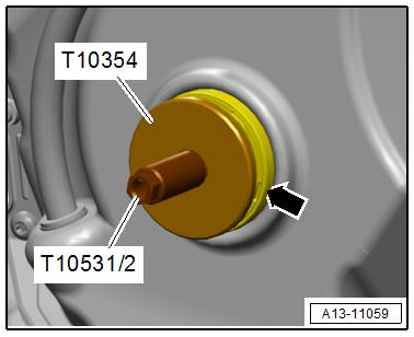
Installing – Clean the running and sealing surface. – Push the seal -arrow- on the Seal Installer - Crankshaft -
T10354- .
• The closed side of the seal points to the Seal Installer - Crank‐shaft - T10354- .
– Push the seal -arrow- with the Seal Installer - Crankshaft -
T10354- on the Tensioning Pins - T10531/2- and place on the lower timing chain cover.
– Additional attach the Press Piece - Gearbox - T10375- and g tighten the Knurled Nut - T10531/4- . – Drive the seal in all the way using the Seal Installer - Crank‐shaft - T10354- .
Note


Protected by copyriht . Copying for pivate or commerci al pur po s e s , i n p a r t r o r in w ho le, is not permitted unless authorised by Volkswagen AG. Volkswagen AG does notguarantee or accept any liabilit y wi th res pect t o t h e c o r r e c t n e ss o f in format ion in this document. Copyright by Volkswagen AG.
♦ Replace the vibration damper bolt. ♦ Replace the O-ring.
Assemble in reverse order of disassembly. Note the following: – Install the vibration damper. Refer to ⇒ “1.4 Vibration Damper, Removing and Installing”, page 47 .

Golf 2015 ➤ , Golf Variant 2015 ➤ Engine Mechanical, Fuel Injection and Ignition - Edition 04.2015
3 Chain Drive
⇒ “3.1 Overview - Camshaft Timing Chain”, page 114 ⇒ “3.2 Overview - Balance Shaft Drive Chain”, page 116 ⇒ “3.3 Camshaft Timing Chain, Removing and Installing”, page 118 ⇒ “3.4 Balance Shaft Drive Chain, Removing and Installing”, page 130
⇒ “3.5 Chain Length, Checking”, page 130 ⇒ “3.6 Valve Timing, Checking”, page 131 3.1 Overview - Camshaft Timing Chain
Note
♦ 01 - Engine Electronics
♦ Guided Functions
♦ 01 - Adaptation After Repair Work On the Chain
Drive
Protected by copyright . Copying for pivate or commerci al pur po s e s , i n p a r t r o r in w ho le, is not permitted unless authorised by Volkswagen AG. Volkswagen AG does notguarantee or accept any liabilit y wi th res pect t o t h e c o r r e c t n e ss o f in format ion in this document. Copyright by Volkswagen AG. 114 Rep. Gr.15 - Cylinder Head, Valvetrain
Golf 2015 ➤ , Golf Variant 2015 ➤ Engine Mechanical, Fuel Injection and Ignition - Edition 04.2015
1 - Bolt ❑ 4 Nm + 90° ❑ Replace after removing 2 - Chain Tensioner ❑ Is under tension ❑ Secure using Tensioner Locking Tool - T40267before removing 3 - Timing Chain Tensioning Rail
4 - Guide Pins ❑ 20 Nm

5 - Bolt ❑ Replace after removing ❑ Tightening specification and sequence for bear‐ing bracket with steel bolts. Refer to ⇒ Fig. ““Tightening Specification and Se‐quence for Bearing Bracket with Steel Bolts”“ , page 116 ❑ Tightening specification and sequence for bear‐ing bracket with alumi‐num bolts. Refer to ⇒ Fig. ““Tightening Protected by copyright . Copying fo pivate or commerci al pur po s e s , i n p a r t r o r in w ho le, is not permitted unless authorised by Volkswagen AG. Volkswagen AG does notguarantee or accept any liabilit y wi th res pect t o t h e c o r r e c t n e ss o f in format ion in this document. Copyright by Volkswagen AG. r Specification and Se‐quence for Bearing Bracket with Aluminum Bolts”“ , page 116 6 - Mounting Sleeve ❑ Depending on the ver‐sion, not present on every bearing bracket ❑ Pulled into the cylinder head with the bolt 7 - Pilot Valves ❑ 35 Nm ❑ Left thread ❑ Removing using Assembly Tool - T10352/28 - Bearing Bracket ❑ Depending on the version with adapter sleeve. Refer to the Parts Catalog for the allocation. ❑ Tightening specification and sequence for bearing bracket with steel bolts. Refer to ⇒ Fig. ““Tightening Specification and Sequence for Bearing Bracket with Steel Bolts”“ , page 116 ❑ Tightening specification and sequence for bearing bracket with aluminum bolts. Refer to ⇒ Fig. ““Tightening Specification and Sequence for Bearing Bracket with Aluminum Bolts”“ , page 9 - Camshaft Timing Chain Guide Rail 10 - Camshaft Housing 11 - Camshaft Timing Chain ❑ Before removing, mark the direction of rotation with paint 12 - Camshaft Timing Chain Guide Rail 13 - Guide Pins ❑ 20 Nm 116
Golf 2015 ➤ , Golf Variant 2015 ➤ Engine Mechanical, Fuel Injection and Ignition - Edition 04.2015
14 - Three Stage Chain Sprocket ❑ Crankshaft ❑ Installed position. Refer to ⇒ Fig. ““Three Stage Chain Sprocket - Installed Position”“ , page 116

Tightening Specification and Sequence for Bearing Bracket with Steel Bolts
– Tighten the bolts in steps in the sequence shown:
Step Bolts 1. -1-
2. -1 to 6Tightening Specifications 3 Nm 9 Nm
Tightening Specification and Sequence for Bearing Bracket with Aluminum Bolts
– Tighten the bolts in steps in the sequence -1 to 6-:
Step Bolts Tightening Specification/Additional Turn
1. -1- through -6-
4 Nm Protectd by copyriht . Copying for pivate or comm rci al pur po s e s , i n p a r t r o r in w ho le, is not permitted unless authorised by Volkswagen AG. Volkswagen AG does notguarantee or accept any liabilit y wi th res pect t o t h e c o r r e c t n e ss o f in format ion in this document. Copyright by Volkswagen AG. 2. -1- through -6- 180° additional turn Three Stage Chain Sprocket - Installed Position • Both surfaces must -arrows- must line up across from each other. e 3.2 Overview - Balance Shaft Drive Chain Note g ♦ After performing work on the chain drive the adaptation value in the engine control module must be adapted. To do this turn on the ignition and select the following menu items on the Ve‐hicle Diagnostic Tester : e♦ 01 - Engine electronics ♦ Guided functions ♦ 01 - Adaptation after repair work on the chain drive
Golf 2015 ➤ , Golf Variant 2015 ➤ Engine Mechanical, Fuel Injection and Ignition - Edition 04.2015
1 - Guide Pin ❑ 20 Nm
ht . Copying fo pivate or commerci al pur po s e s , i Protected by copyri

2 - Tensioning Rail p a r t o r in w ho le, is not permitted unless authorised by Volkswagen AG. Volkswagen AG does notguarantee or accept any liabilit y wi th res pect t o t h e c o r r e c t n e ss o f ❑ For the timing chain 3 - Balance Shaft ❑ Exhaust side ❑ Must be replaced after removing ❑ Lubricate the bearing with engine oil ❑ Replacing. Refer to ⇒ “4.2.2 Balance Shaft Exhaust Side, Remov‐ing and Installing”, page 73 . n 4 - Guide Pin ❑ 20 Nm 5 - Guide Rail ❑ For the timing chain r r 6 - Chain Tensioner ❑ 85 Nm ❑ Install with locking fluid. Refer to the Parts Cata‐log. 7 - Seal g 8 - Cylinder Block 9 - O-Ring ❑ Coat with engine oil 10 - Mounting Pin in format ion in this document. Copyright by Volkswagen AG. ❑ Lubricate with engine oil ❑ Installed position. Refer to ⇒ Fig. ““Mounting Pins - Installation Position”“ , page 118 11 - Intermediate Sprocket ❑ The intermediate sprocket must be replaced if the bolt -item 13- ⇒ Item 13 (page 117) is loosened. 12 - Thrust Washer
13 - Bolt ❑ Replace after removing ❑ The intermediate sprocket -item 11- ⇒ Item 11 (page 117) must be replaced if the bolt is loosened. ❑ Tightening sequence. Refer to ⇒ Fig. ““Intermediate Sprocket Tightening Sequence”“ , page 118 14 - Guide Rail ❑ For balance shaft timing chain 15 - Guide Pin ❑ 20 Nm
16 - Balance Shaft ❑ Intake side ❑ Must be replaced after removing ❑ Lubricate the bearing with engine oil ❑ Replacing. Refer to ⇒ “4.2.1 Balance Shaft Intake Side, Removing and Installing”, page 70 . 17 - Three Stage Chain Sprocket ❑ Installed position. Refer to ⇒ Fig. ““Three Stage Chain Sprocket - Installed Position”“ , page 116

Protectd by copyright . Copying fo pivate or commerci al pur po e s , i n p a r t r o r in w ho le, is not permitted unless authorised by Volkswagen AG. Volkswagen AG does notguarantee or accept any liabilit y wi th res pect t o t h e c o r r e c t n e ss o f in format ion in this document. Copyright by Volkswagen AG. 18 - Balance Shaft Drive Chain ❑ Removing and installing. Refer to ⇒ “3.4 Balance Shaft Drive Chain, Removing and Installing”, page 130 . s Mounting Pins - Installation Position • Replace and lubricate the O-Ring -1• The alignment pin -arrow- for the bearing pins must engage in the hole in the cylinder block. • Lubricate the bearing pins r Intermediate Sprocket Tightening Sequence Note e♦ Always replace the intermediate sprocket. Otherwise the backlash will not adjust itself and it could result in engine dam‐Golf 2015 ➤ , Golf Variant 2015 ➤ Engine Mechanical, Fuel Injection and Ignition - Edition 04.2015 age. ♦ The new intermediate sprocket has an anti-friction coating that wears off after a short period of use, which automatically ad‐justs the backlash.
Step
1. 2.
3. 4. Bolts
-1-1-
-1-1Tightening Specification/Addi‐tional Turn 10 Nm The intermediate sprocket must not have any play. Loos‐en and tighten it again if nec‐essary. 25 Nm Turn an additional 90°
Special tools and workshop equipment required ♦ Assembly Tool - T10352/2♦ Counterhold - Vibration Damper - T10355♦ Locking Pin (3 pc.) - T40011♦ Chain Tensioner Lever - T40243-
♦ Tensioner Locking Tool - T40267♦ Camshaft Locks - T40271-
♦ Adapter - T40266♦ Assembly Tool - T10531♦ Individual components of the Assembly Tool - T10531- : ♦ Mount - T10531/1-
Golf 2015 ➤ , Golf Variant 2015 ➤ Engine Mechanical, Fuel Injection and Ignition - Edition 04.2015
♦ Tensioning Pins - T10531/2♦ Turning Over Tool - T10531/3♦ Collar Nut - T10531/4-

Caution
Protected by copyright . Copying fo pivate or co merci al pur po s e s , i n p a r t r o r in w ho le, is not permitted unless authorised by Volkswagen AG. Volkswagen AG does notguarantee or accept any liabilit y wi th res pect t o t h e c o r r e c t n e ss o f in format ion in this document. Copyright by Volkswagen AG. This procedure contains mandatory replaceable parts. Refer to component overview prior to starting procedure. m Mandatory Replacement Parts ♦ Bolts - Bearing Bracket ♦ Bolt - Intermediate Sprocket Removing – Support the engine in its installed position. Refer to ⇒ “2.5 Engine, Supporting in Installed Position”, page 33 . – Remove the engine bracket. Refer to ⇒ “2.2 Engine Mount, Removing and Installing”, page 30 . – Remove engine support. Refer to ⇒ “1.6 Engine Support, Removing and Installing”, page 55 . – Remove timing chain upper cover. Refer to ⇒ “2.2.1 Upper Timing Chain Cover, Removing and Installing”, page 106 . – Remove the noise insulation. Refer to ⇒ Body Exterior; Rep. Gr. 66 ; Noise Insulation; Overview - Noise Insulation . r – Remove the right wheel housing liner front section. Refer to ⇒ Body Exterior; Rep. Gr. 66 ; Wheel Housing Liner; Front Wheel Housing Liner, Removing and Installing . – Turn the vibration damper with the Counterhold - Vibration Damper - T10355- to the “Top Dead Center (TDC) point”. • The markings -1- on the camshaft chain sprockets must be opposite the markings -2 and 3-. • The notch on the vibration damper and the marking on the lower cover for timing chain -arrow- must be opposite one an‐other. – Remove the lower timing chain cover. Refer to ⇒ “2.2.2 Lower Timing Chain Cover, Removing and Installing”, page 108 . Note
The pilot valve has left-hand threads.
Golf 2015 ➤ , Golf Variant 2015 ➤ Engine Mechanical, Fuel Injection and Ignition - Edition 04.2015
– Remove the left and right pilot valves using the Assembly Tool - T10352/2- in the direction of the -arrow-.
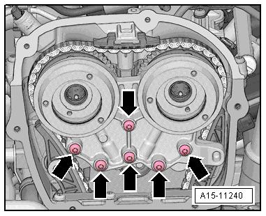
– Remove the bolts -arrows- and remove the bearing bracket.
– Remove the bolts -arrows-.


Protected by copyright . Copying for pivate or commerci al pur po s e s , i

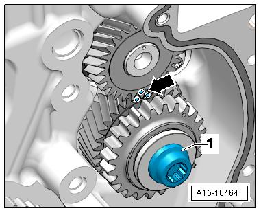
p a r t o r in w ho le, is not permitted unless authorised by Volkswagen AG. Volkswagen AG does notguarantee or accept any liabilit y wi th res pect t o t h e c o r r e c t n e ss o f – Install the Chain Tensioner Lever - T40243- in direction of -arrows-. n – Press the chain tensioner locking ring -1- together and hold it. – Slowly press and hold the Chain Tensioner Lever - T40243in the direction of -arrow-. r in format ion in this document. Copyright by Volkswagen AG.
Golf 2015 ➤ , Golf Variant 2015 ➤ Engine Mechanical, Fuel Injection and Ignition - Edition 04.2015
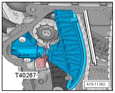
– Secure the chain tensioner with the Tensioner Locking Tool -
T40267- .
– Remove the Chain Tensioner Lever - T40243- .
– Bolt the Camshaft Lock - Component 2 - T40271/2- to the cyl‐inder head and slide into the splines on the chain sprocket in the direction of the -arrow 2-. Rotate the intake camshaft with the Adapter - T40266- -1- if necessary. – Install the Camshaft Lock - Component 1 - T40271/1- on the cylinder head. For the following steps a second technician is necessity.
Protected by copyright . Copying for pivate or commerci al pur po s e s , i n p a r t r o r in w ho le, is not permitted unless authorised by Volkswagen AG. Volkswagen AG does notguarantee or accept any liabilit y wi th res pect t o t h e c o r r e c t n e ss o f in format ion in this document. Copyright by Volkswagen AG. – Hold the exhaust camshaft with the Adapter - T40266- in the direction of the -arrow A-. Remove the bolt -1- and guide the tensioning rail -2- downward. Turn the camshaft clockwise in direction of -arrow A- until the Camshaft Lock - Component 1 - T40271/1- can be pushed in the chain sprocket splines -C-. – Remove the guide rail -1- by unlocking the latch -arrow- with a screwdriver and pushing the guide rail forward.


