
7 minute read
7.2 High Pressure Pump, Removing and Installing


Golf 2015 ➤ , Golf Variant 2015 ➤ Engine Mechanical, Fuel Injection and Ignition - Edition 04.2015
– Carefully slide the Low Fuel Pressure Sensor - G410- -1- all the way into the fuel rail. – To secure the Low Fuel Pressure Sensor - G410- , slide the clip -2- into the groove. – Connect the connector.
Tightening Specifications ♦ Refer to ⇒ “4.2.2 Overview - Intake Manifold Lower Section with Fuel
Rail, Multiport Fuel Injection”, page 302 .
Protected by copyright . Copying for pivate or commerci al pur po s e s , i n p a r t r o r in w ho le, is not permitted unless authorised by Volkswagen AG. Volkswagen AG does notguarantee or accept any liabilit y wi th res pect t o t h e c o r r e c t n e ss o f in format ion in this document. Copyright by Volkswagen AG.
Golf 2015 ➤ , Golf Variant 2015 ➤ Engine Mechanical, Fuel Injection and Ignition - Edition 04.2015
6 Engine Control Module
⇒ “6.1 Engine Control Module J623 , Removing and Installing”, page 321 6.1 Engine Control Module - J623- , Remov‐ing and Installing
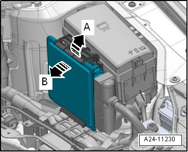
⇒ “6.1.1 Engine Control Module J623 , Removing and Installing, without Protective Housing”, page 321 ⇒ “6.1.2 Engine Control Module J623 with Protective Housing, Removing and Installing”, page 322 Protectd by copyright . Copying fo pivate or commerci al p r po s s , i n p a r t r o r in w ho le, is not permitted unless authorised by Volkswagen AG. Volkswagen AG does notguarantee or accept any liabilit y wi th res pect t o t h e c o r r e c t n e ss o f in format ion in this document. Copyright by Volkswagen AG. 6.1.1 Engine Control Module - J623- , Remov‐ing and Installing, without Protective Housing Special tools and workshop equipment required ♦ Vehicle Diagnostic Tester Removing – Turn on the ignition and select the following menu items on the Vehicle Diagnostic Tester : ♦ 01 - Engine Electronics ♦ Guided Functions e♦ 01 - Engine Control Module Replacing u – Turn off the ignition and remove the key. Note r Touching the engine control module with the battery positive ter‐minal damages the engine control module. For this reason the battery must be disconnected before removing the engine control module from its mount. Refer to ⇒ Electrical Equipment; Rep. Gr. 27 ; Battery; Battery, Disconnecting and Connecting . e – Release the retainers in direction of -arrow A- and remove the Engine Control Module - J623- in direction of -arrow B-. – Unlock and disconnect the connectors from the Engine Con‐trol Module - J623- .
Golf 2015 ➤ , Golf Variant 2015 ➤ Engine Mechanical, Fuel Injection and Ignition - Edition 04.2015

Installing Install in reverse order of removal. Note the following: – Place the Engine Control Module - J623- in the bracket with the lower edge forward in direction of -arrow A- and locked on the upper edge. • The ribs on the ECM must be engaged in the upper and lower Protectd by copyright . Copying fo pivate or co merci al pur po e s , i n p a r t r o r in w ho le, is not permitted unless authorised by Volkswagen AG. Volkswagen AG does notguarantee or accept any liabilit y wi th res pect t o t h e c o r r e c t n e ss o f in format ion in this document. Copyright by Volkswagen AG. recesses on the bracket -B arrows-. – Connect the battery. Refer to ⇒ Electrical Equipment; Rep. Gr. 27 ; Battery; Battery, Disconnecting and Connecting . Perform the Following after Installing a New ECM – Turn on the ignition and select the following menu items on the Vehicle Diagnostic Tester : ♦ 01 - Engine Electronics ♦ Guided Functions ♦ 01 - Engine Control Module Replacing s 6.1.2 Engine Control Module - J623- with Pro‐tective Housing, Removing and Instal‐ling m Special tools and workshop equipment required ♦ Wiring Harness Repair Set - Hot Air Blower - VAS1978/14Awith nozzle attachment from the Wiring Harness Repair Set VAS1978B- . r ♦ Mini-grinder, commercially available ♦ Vehicle Diagnostic Tester Caution e This procedure contains mandatory replaceable parts. Refer to component overview prior to starting procedure.
Mandatory Replacement Parts ♦ Bolts - Shear, Protective Housing Removing – Turn on the ignition and select the following menu items on the
Vehicle Diagnostic Tester :
♦ 01 - Engine Electronics
♦ Guided Functions
♦ 01 - Engine Control Module Replacing
– Turn off the ignition and remove the key.
Note
Touching the engine control module with the battery positive ter‐minal damages the engine control module. For this reason the battery must be disconnected before removing the engine control module from its mount. Refer to ⇒ Electrical Equipment; Rep. Gr. 27 ; Battery; Battery, Disconnecting and Connecting .
Golf 2015 ➤ , Golf Variant 2015 ➤ Engine Mechanical, Fuel Injection and Ignition - Edition 04.2015
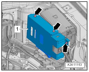
Remove the shear bolts -arrows- to remove the protective hous‐ing -1- as follows:
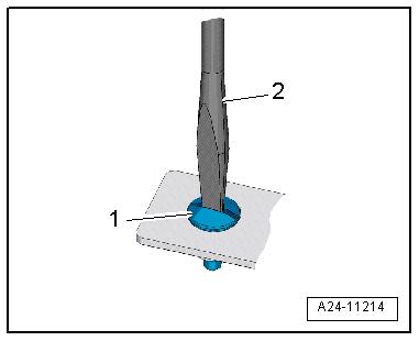
– Make a recess in the head of the shear bolt -1- for a screw‐driver. Use a mini-grinder -2- to make the recess.

Note
Protected by copyriht . Copying fo pivate or commerci al pur po s e s , i n p a r t r o r in w ho le, is not permitted unless authorised by Volkswagen AG. Volkswagen AG does notguarantee or accept any liabilit y wi th res pect t o t h e c o r r e c t n e ss o f in format ion in this document. Copyright by Volkswagen AG. r The shear bolts were installed with a locking fluid. For this reason, the threads must be heated with the heat gun to remove both bolts. g – Adjust the settings on the hot air gun as shown. That means the temperature potentiometer -2- set to maximum heat and the two-stage airflow switch -3- set to level 3. NOTICE

Risk of damaging the surrounding components using the hot air gun. Overheating is possible. – If necessary, cover the surrounding components.
– Warm the head of the shear bolt -1- for 20 to 30 seconds.

Golf 2015 ➤ , Golf Variant 2015 ➤ Engine Mechanical, Fuel Injection and Ignition - Edition 04.2015
– Remove the shear bolt -1- with a screwdriver -2-.
– Remove the protective housing from the Engine Control Mod‐ule - J623- .
– Release the retainers in direction of -arrow A- and remove the
Engine Control Module - J623- in direction of -arrow B-. – Unlock and disconnect the connectors from the Engine Con‐trol Module - J623- .
Installing Install in reverse order of removal. Note the following: – Place the Engine Control Module - J623- in the bracket with the lower edge forward in direction of -arrow A- and locked on the upper edge. – Engine Control Module - J623- must be installed again with protective housing. – Clean any locking fluid still in the threaded holes for the shear bolt. Cleaning can be performed with a thread cutter (tap). – Always use new shear bolts. – Connect the battery. Refer to ⇒ Electrical Equipment; Rep.
Gr. 27 ; Battery; Battery, Disconnecting and Connecting . Perform the Following after Installing a New ECM – Turn on the ignition and select the following menu items on the
Vehicle Diagnostic Tester :
Protected by opyright . Copying for pivate or commerci al pur po s e s , i n p a r t r o r in w ho le, is not permitted unless authorised by Volkswagen AG. Volkswagen AG does notguarantee or accept any liabilit y wi th res pect t o t h e c o r r e c t n e ss o f in format ion in this document. Copyright by Volkswagen AG. ♦ 01 - Engine Electronics ♦ Guided Functions ♦ 01 - Engine Control Module Replacing c324 Rep. Gr.24 - Multiport Fuel Injection


