6 minute read
6 Special Tools


Golf 2015 ➤ , Golf Variant 2015 ➤ Engine Mechanical, Fuel Injection and Ignition - Edition 04.2015
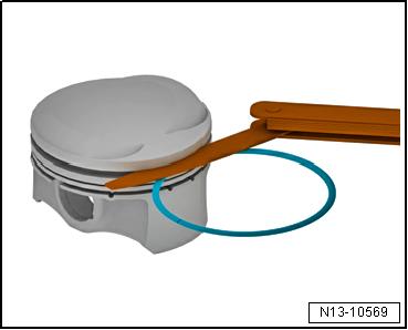
6 - Locking Ring ❑ Replace after removing 7 - Piston Pin ❑ Coat with oil before installing 8 - Piston ❑ Removing and installing. Refer to ⇒ “5.2 Pistons, Removing and Installing”, page 78 . ❑ Mark installed position and cylinder allocation ❑ Arrow on piston face points toward belt pulley side ❑ Check piston and cylinder bore. Refer to ⇒ “5.3 Pistons and Cylinder Bore, Checking”, page 80 . 9 - Compression Rings ❑ Use piston ring pliers (commercially available) for removing and installing ❑ Offset gaps by 120° ❑ Installed Position: “TOP” “R” mark must face up toward piston crown ❑ Ring Gap/Groove Clearance, Checking. Refer to ⇒ “5.3 Pistons and Cylinder Bore, Checking”, page 80 . 10 - Oil Scraping Ring ❑ Two-part ❑ Install offset gaps by 120° to the neighboring compression ring ❑ The “TOP” or “R” marking must face toward the piston crown. ❑ Checking the ring gap. Refer to ⇒ “5.3 Pistons and Cylinder Bore, Checking”, page 80 . ❑ Side clearance cannot be measured.
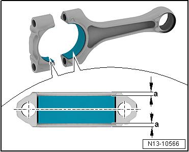
11 - Connecting Rod ❑ Always replace as a set. ❑ Mark affiliation to cylinder -A❑ Installed position: the markings -B- face the belt pulley side ❑ Disconnect the new connecting rod. Refer to ⇒ “5.4 New Connecting Rod, Separating”, page 84 . ❑ Radial play, measuring. Refer to ⇒ “5.5 Connecting Rods, Checking Radial Clearance”, page 84 .
Installed Position of Bearing Shell – Place bearing shells centrally into connecting rod and con‐necting rod bearing cap. Dimension -a- must be the same at left and right.
Protected by copyright . Copying for pivate or comm rci al p r po s e , i n p a r t r o r in w ho le, is not permitted unless authorised by Volkswagen AG. Volkswagen AG does notguarantee or accept any liabilit y wi th res pect t o t h e c o r r e c t n e ss o f in format ion in this document. Copyright by Volkswagen AG. s 5.2 Pistons, Removing and Installing u Special tools and workshop equipment required ♦ Pilot Drift - VW222Ae♦ Piston ring compressor, commercially available 78 Rep. Gr.13 - Crankshaft, Cylinder Block
Protected by copyright . Copying fo pivate or co merci al pur po s e s , i n p a r t r o r in w ho le, is not permitted unless authorised by Volkswagen AG. Volkswagen AG does notguarantee or accept any liabilit y wi th res pect t o t h e c o r r e c t n e ss o f in format ion in this document. Copyright by Volkswagen AG. Caution This procedure contains mandatory replaceable parts. Refer to component overview prior to starting procedure. m Mandatory Replacement Parts ♦ Bolts - Connecting Rod ♦ Ring - Locking Removing – Secure the engine to the Engine And Transmission Holder VAS6095- . Refer to ⇒ “1.3 Engine, Securing on Engine and Transmission Holder”, page 23 . – Remove the cylinder head. Refer to ⇒ “1.3 Cylinder Head, Removing and Installing”, page 94 . – Remove the oil pan upper section. Refer to ⇒ “1.4 Oil Pan Upper Section, Removing and Installing”, page 185 . r – Mark the installed position and cylinder allocation. – Mark installed position and connecting rod cylinder -item 11⇒ Item 11 (page 78) . – Remove the connecting rod bearing cap and pull the piston and connecting rod upward. Note Golf 2015 ➤ , Golf Variant 2015 ➤ Engine Mechanical, Fuel Injection and Ignition - Edition 04.2015
Warm the piston to approximately 60 °C (140 °F) if it is difficult to move the piston pin.
– Remove the locking ring from the eye of the piston bolt. – Remove the piston pin using the Pilot Drift - VW222A- . Installing Install in reverse order of removal. Note the following:
Note
♦ Replace the bolts were tightened with an additional turn. ♦ Arrow on piston face points toward belt pulley side. ♦ Offset the piston ring gap by 120°.
– Coat the contact surfaces on the bearing shells with oil. – Install the piston with a piston ring compressor. Pay attention to the installed position -item 8- ⇒ Item 8 (page 78) . – Install the connecting rod bearing cap. Pay attention to the in‐stalled position -item 2- ⇒ Item 2 (page 77) . – Install the cylinder head. Refer to ⇒ “1.3 Cylinder Head, Removing and Installing”, page 94 . – Install the oil pan upper section. Refer to ⇒ “1.4 Oil Pan Upper Section, Removing and Installing”, page 185 .
Golf 2015 ➤ , Golf Variant 2015 ➤ Engine Mechanical, Fuel Injection and Ignition - Edition 04.2015
d by copyright . Co ying for pivate or commerci al pur po s e s , i Protect

p a r t o r in w ho le, is not permitted unless authorised by Volkswagen AG. Volkswagen AG does notguarantee or accept any liabilit y wi th res pect t o t h e c o r r e c t n e ss o f Tightening Specifications ♦ Refer to ⇒ “5.1 Overview - Piston and Connecting Rod”, page 77 . 5.3 Pistons and Cylinder Bore, Checking ⇒ “5.3.1 Pistons and Cylinder Bore, Checking, Engine Codes CXBA, CXBB, CNSA and CNSB”, page 80 ⇒ “5.3.2 Piston and Cylinder Bore, Checking, Engine Codes CNTA, CXCA, CXCB”, page 82 n 5.3.1 Pistons and Cylinder Bore, Checking, Engine Codes CXBA, CXBB, CNSA and CNSB Pistons, Checking r p Special tools and workshop equipment required ♦ Outside Micrometer - 75-100mm - VAS6071e – Measure approximately 15 mm in from the lower edge at a 90° angle to the piston pin axis using a micrometer. in format ion in this document. Copyright by Volkswagen AG. ♦ Deviation from specified size: maximum 0.04 mm
Basic Dimension
Piston Diameter in mm 82.465 1) • 1) Measurements without graphite coating (thickness = 0.02 mm). The graphite coating wears off.
Checking Piston Ring Gap
Special tools and workshop equipment required ♦ Feeler Gauge – Push piston ring squarely from above down to approximately 15 mm from bottom end of cylinder. To do this use a piston without rings.
Piston Ring Dimensions in mm Compression ring Oil scraping ring New Wear Limit
0.20 to 0.40 0.80 0.25 to 0.50 0.80

Golf 2015 ➤ , Golf Variant 2015 ➤ Engine Mechanical, Fuel Injection and Ignition - Edition 04.2015
Piston Ring Groove Clearance, Checking
Special tools and workshop equipment required ♦ Feeler Gauge – Clean the piston ring groove before checking.
Piston Ring Dimensions in mm New Wear Limit
1st Compression ring 0.06 to 0.09 2nd Compression ring 0.03 to 0.06 0.20 0.15
Oil scraping rings Cannot be measured
Check Cylinder Bore

Protected by copyriht . Copying for pivate or co merci al p r po s e s , i n p a r t r o r in w ho le, is not permitted unless authorised by Volkswagen AG. Volkswagen AG does notguarantee or accept any liabilit y wi th res pect t o t h e c o r r e c t n e ss o f in format ion in this document. Copyright by Volkswagen AG. u Special tools and workshop equipment required ♦ Cylinder Dial Bore Gauge - VAS6078NOTICE m Risk of damaging the cylinder bore surface through incorrect handling. – Never handle the cylinder bore with service equipment (drill‐ing, honing, grinding). g – Using a Cylinder Dial Bore Gauge - VAS6078- measure in a diagonal sequence at three positions transversely -A- and lon‐gitudinally -B-. ♦ Deviation from specified size: maximum 0.08 mm


