13 minute read
6 Special Tools


Golf 2015 ➤ , Golf Variant 2015 ➤ Engine Mechanical, Fuel Injection and Ignition - Edition 04.2015
4.6 Valve Stem Seals, Removing and In‐stalling
⇒ “4.6.1 Valve Stem Seals, Removing and Installing, Cylinder Head Installed”, page 163 . ⇒ “4.6.2 Valve Shaft Seals, Removing and Installing, Cylinder Removed”, page 166 . 4.6.1 Valve Stem Seals, Removing and In‐stalling, Cylinder Head Installed
Special tools and workshop equipment required ♦ Spark Plug Removal Tool - 3122B♦ Puller - Valve Seal - 3364-
♦ Seal Installer - Valve Stem - 3365-
♦ Valve Cotter Tool Kit - Adapter - T40012♦ Torque Wrench 1331 5-50Nm - VAG1331♦ Valve Keeper Tool Kit - VAS5161A♦ Valve Cotter Tool Kit - Guide Plate 19B - VAS5161/19B-
♦ Valve Cotter Tool Kit Knurled Thumb Screws M6 -
VAS5161/12-
♦ Punch - VAS5161/3A-
Remove Valve Stem Seals
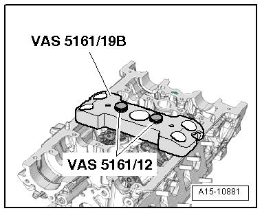
– Remove the camshafts. Refer to ⇒ “4.2 Camshaft, Removing and Installing”, page 136 . – Mark the allocation of the roller rocker lever and the hydraulic adjusting elements so they can be installed again. Protected by copyright . Copying for pivate or commerci al pur po s e s , i n p a r t r o r in w ho le, is not permitted unless authorised by Volkswagen AG. Volkswagen AG does notguarantee or accept any liabilit y wi th res pect t o t h e c o r r e c t n e ss o f in format ion in this document. Copyright by Volkswagen AG. – If necessary, remove the roller rocker levers with the hydraulic adjusting elements and place them on a clean surface. – Remove the spark plugs using a Spark Plug Removal Tool 3122B- . – Install the Valve Cotter Tool Kit - Guide Plate 19B VAS5161/19B- with the Valve Cotter Tool Kit Knurled Thumb Screws M6 - VAS5161/12- as shown on the cylinder head. – Move piston for that cylinder to “bottom dead center position”.
Golf 2015 ➤ , Golf Variant 2015 ➤ Engine Mechanical, Fuel Injection and Ignition - Edition 04.2015
– Install the Valve Cotter Tool Kit - Adapter - T40012- in the spark plug threads. – Connect compressed air with at least 6 bar (87 psi) pressure. – Loosen stuck valve retainers using a Punch - VAS5161/3Aand a plastic hammer.

For Intake Side
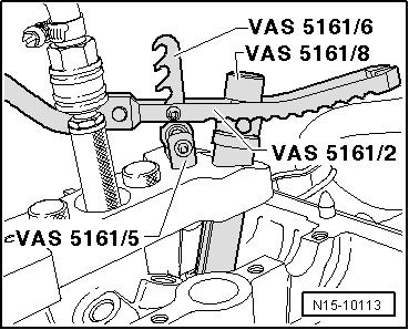

– Install the Valve Cotter Tool Kit - Retainer - VAS5161/6- with
Valve Cotter Tool Kit - Guide Forks M6/M8 Threaded -
VAS5161/5- in the center thread of the Valve Cotter Tool Kit Protected by copyright . Copying fo pivate or commerci al p r po s e s , i n p a r t r o r in w ho le, is not permitted unless authorised by Volkswagen AG. Volkswagen AG does notguarantee or accept any liabilit y wi th res pect t o t h e c o r r e c t n e ss o f in format ion in this document. Copyright by Volkswagen AG. Guide Plate 19B - VAS5161/19B- . – Place the Valve Cotter Tool Kit - Assembly Cartridge VAS5161/8- in the Valve Cotter Tool Kit - Guide Plate 19B VAS5161/19B- . – Engage the Pressure Fork With Lever for Assembly Cartridge - VAS5161/2- on the Retainer - VAS5161/6- . For Exhaust Side – Install the Valve Cotter Tool Kit - Retainer - VAS5161/6- with Valve Cotter Tool Kit - Guide Forks M6/M8 Threaded VAS5161/5- in the outer thread of the Valve Cotter Tool Kit Guide Plate 19B - VAS5161/19B- . u – Press down the Assembly Cartridge - VAS5161/8A- and at the same time turn the knurled thumb screw on the Assembly Cartridge - VAS5161/8A- to the right until the points engage in the valve retainers. r – Move the knurled thumb screw back and forth slightly. This presses the valve retainers apart and captures them in the in‐stallation cartridge. – Release the Pressure Fork With Lever For Assembly Car‐tridge - VAS5161/2- . – Remove the Assembly Cartridge - VAS5161/8A- .
Golf 2015 ➤ , Golf Variant 2015 ➤ Engine Mechanical, Fuel Injection and Ignition - Edition 04.2015
– Remove the valve stem seals using Puller - Valve Seal 3364- .
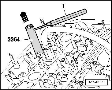


Protected by copyright . Copying for pivate or co mer i al pur po e s , i n p a r t r o r in w ho le, is not permitted unless authorised by Volkswagen AG. Volkswagen AG does notguarantee or accept any liabilit y wi th res pect t o t h e c o r r e c t n e ss o f in format ion in this document. Copyright by Volkswagen AG. – If the Puller - Valve Seal - 3364- cannot be used because there is not enough space, drive the roll pin -arrow- out using a drift and remove the impact attachment. s– Position the lower part of the Puller - Valve Seal - 3364- on the valve stem seal. c – Place the drift -1- in the hole in the lower section of the removal tool. m – Position the lever on the removal tool and remove the valve stem seal in direction of -arrow-. Install Valve Stem Seals – Place the plastic sleeve -A- that is attached to valve stem seals -B- on valve stem.
– Lightly oil the valve stem seal. – Slide the valve stem seal onto the plastic sleeve. – Carefully press the valve stem seal onto the valve guide with the Seal Installer - Valve Stem - 3365- .
– Remove plastic sleeve. – Insert the valve spring and valve spring plate. – Connect the Valve Keeper Tool Kit - VAS5161A- as illustrated.

Golf 2015 ➤ , Golf Variant 2015 ➤ Engine Mechanical, Fuel Injection and Ignition - Edition 04.2015
Intake Side

Protected by copyright . Copying fo pivate r commer i al pur po s e s , i n p a r t r o r in w ho le, is not permitted unless authorised by Volkswagen AG. Volkswagen AG does notguarantee or accept any liabilit y wi th res pect t o t h e c o r r e c t n e ss o f in format ion in this document. Copyright by Volkswagen AG. Exhaust Side Note c ♦ If the valve retainers were removed from the assembly car‐tridge, they must then be inserted into the Valve Insertion Device - VAS5161/18- . o ♦ Press the Assembly Cartridge -VAS5161/8A- onto the inser‐tion device from above and capture the valve retainers. r – Press the Valve Keeper Tool Kit Assembly Cartridge VAS5161/8- down with the Valve Keeper Tool Kit Pressure Fork with Lever for Assembly Cartridge - VAS5161/2- and ro‐tate the cartridge knurled thumb screw back and forth while pulling up. – Release the Pressure Fork with Lever for Assembly Cartridge - VAS5161/2- with the knurled thumb screw pulled. – Remove the Valve Keeper Tool Kit - VAS5161A- .
Further assembly is performed in the reverse order of removal, thereby observing the following: – Install the camshafts. Refer to ⇒ “4.2 Camshaft, Removing and Installing”, page 136 .
Special tools and workshop equipment required ♦ Puller - Valve Seal - 3364-
♦ Seal Installer - Valve Stem - 3365-
♦ Valve Keeper Tool Kit - VAS5161A♦ Valve Cotter Tool Kit - Guide Plate 19B - VAS5161/19B-

Protectd by copyright . Copyin for pivate or co merci al p r po s e s , i n p a r t r o r in w ho le, is not permitted unless authorised by Volkswagen AG. Volkswagen AG does notguarantee or accept any liabilit y wi th res pect t o t h e c o r r e c t n e ss o f in format ion in this document. Copyright by Volkswagen AG. ♦ Engine And Transmission Holder - VAS6095♦ Cylinder Head Tensioning Device - VAS6419Remove Valve Stem Seals u – Remove the camshafts. Refer to ⇒ “4.2 Camshaft, Removing and Installing”, page 136 . – Mark the allocation of the roller rocker lever and the hydraulic adjusting elements so they can be installed again. – If necessary, remove the roller rocker levers with the hydraulic adjusting elements and place them on a clean surface. – Insert the Cylinder Head Tensioning Device - VAS6419- in the Engine And Transmission Holder - VAS6095- . – Tension the cylinder head on the cylinder head tensioning de‐vice, as illustrated. m – Connect the cylinder head tensioning device to the com‐pressed air. – Slide the air cushion with the lever -arrow- under the combus‐tion chamber onto the valve stem seal that will be removed. g – Let enough compressed air flow into the air cushion until it contacts the valve plate. e – Install the Valve Cotter Tool Kit - Guide Plate 19B VAS5161/19C- with the Valve Cotter Tool Kit Knurled Thumb Screws M6 - VAS5161/12- as shown on the cylinder head. – Insert the Punch - VAS5161/3- in the guide plate and loosen the stuck valve retainers with a plastic mallet. Golf 2015 ➤ , Golf Variant 2015 ➤ Engine Mechanical, Fuel Injection and Ignition - Edition 04.2015

For Intake Side
– Install the Valve Cotter Tool Kit - Retainer - VAS5161/6- with
Valve Cotter Tool Kit - Guide Forks M6/M8 Threaded -
VAS5161/5- in the center thread of the Valve Cotter Tool Kit -
Guide Plate 19B - VAS5161/19B- .
– Place the Valve Cotter Tool Kit - Assembly Cartridge -
VAS5161/8- in the Valve Cotter Tool Kit - Guide Plate 19B -
VAS5161/19B- .
– Engage the Pressure Fork With Lever for Assembly Cartridge - VAS5161/2- on the Retainer - VAS5161/6- .
Golf 2015 ➤ , Golf Variant 2015 ➤ Engine Mechanical, Fuel Injection and Ignition - Edition 04.2015
For Exhaust Side
– Install the Retainer - VAS5161/6- with Forks M6/M8 Threaded - VAS5161/5- in the outer thread of the Valve Cotter Tool Kit - Guide Plate 19B - VAS5161/19B- .
– Press down the Assembly Cartridge - VAS5161/8A- and at the same time turn the knurled thumb screw on the Assembly
Cartridge - VAS5161/8A- to the right until the points engage in the valve retainers.
– Move the knurled thumb screw back and forth slightly. This Protectd by copyright . Copying for pivate or commerci al pur po s e s , i n p a r t r o r in w ho le, is not permitted unless authorised by Volkswagen AG. Volkswagen AG does notguarantee or accept any liabilit y wi th res pect t o t h e c o r r e c t n e ss o f in format ion in this document. Copyright by Volkswagen AG. presses the valve retainers apart and captures them in the in‐stallation cartridge. – Release the Pressure Fork With Lever For Assembly Car‐tridge - VAS5161/2- . – Remove the Assembly Cartridge - VAS5161/8A- . – Remove the valve stem seals using Puller - Valve Seal 3364- . Install Valve Stem Seals e– Place the plastic sleeve -A- that is attached to valve stem seals -B- on valve stem.
– Lightly oil the valve stem seal. – Slide the valve stem seal onto the plastic sleeve. – Carefully press the valve stem seal onto the valve guide with the Seal Installer - Valve Stem - 3365- .
– Remove plastic sleeve. – Insert the valve spring and valve spring plate. – Install the Valve Keeper Tool Kit - VAS5161A- as illustrated.
Intake Side
Exhaust Side Golf 2015 ➤ , Golf Variant 2015 ➤ Engine Mechanical, Fuel Injection and Ignition - Edition 04.2015
Note
Protected by copyright . Copying for pivate or co merci al pur po s e s , i n p a r t r o r in w ho le, is not permitted unless authorised by Volkswagen AG. Volkswagen AG does notguarantee or accept any liabilit y wi th res pect t o t h e c o r r e c t n e ss o f in format ion in this document. Copyright by Volkswagen AG. ♦ If the valve retainers were removed from the assembly car‐tridge, they must then be inserted into the Valve Insertion Device - VAS5161/18- . ♦ Press the Assembly Cartridge - VAS5161/8A- onto the inser‐tion device from above and capture the valve retainers. m – Press the Valve Keeper Tool Kit Assembly Cartridge VAS5161/8- down with the Valve Keeper Tool Kit Pressure Fork with Lever for Assembly Cartridge - VAS5161/2- and ro‐tate the cartridge knurled thumb screw back and forth while pulling up. – Release the Pressure Fork with Lever for Assembly Cartridge - VAS5161/2- with the knurled thumb screw pulled. – Remove the Valve Keeper Tool Kit - VAS5161A- . Assemble in reverse order of disassembly. Note the following: – Install the camshafts. Refer to ⇒ “4.2 Camshaft, Removing and Installing”, page 136 .
Golf 2015 ➤ , Golf Variant 2015 ➤ Engine Mechanical, Fuel Injection and Ignition - Edition 04.2015
5 Intake and Exhaust Valves
⇒ “5.1 Valve Guides, Checking”, page 170 . ⇒ “5.2 Valves, Checking”, page 170 . ⇒ “5.3 Valve Dimensions”, page 170 . 5.1 Valve Guides, Checking

r po s e s , i rci al p mm ht . Copying for pivate or c ected by copyri Pro
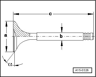
Special tools and workshop equipment required ♦ Dial Gauge Holder - VW387♦ Dial Gauge - 0-10mm - VAS6079Test Sequence – Insert the valve into guide. Valve stem end must be flush with the guide. Due to differences in valve stem diameter, make sure that only intake valves are used to check intake valve guides, and only exhaust valves are used to check exhaust valve guides. – Determine tip clearance. p a r t o r in w ho le, is not permitted unless authorised by Volkswagen AG. Volkswagen AG does notguarantee or accept any liabilit y wi th res pect t o t h e c o r r e c t n e ss o f Wear Limit Intake Valve Guide Exhaust Valve Guide 0.80 mm 0.80 mm Note ♦ If wear limit is exceeded, measure using new valves. Replace the cylinder head if the wear limit is still exceeded. ♦ If the valve is replaced during a repair, use a new valve for measurement. n 5.2 Valves, Checking u – Check valves at stem and seating surface for traces of wear. – If there are clear traces of wear, replace valve. r in format ion in this document. Copyright by Volkswagen AG. e 5.3 Valve Dimensions o Valve Dimensions Note g Intake and exhaust valves must not be reworked. Only lapping is permitted. Dimension tIntake Valve Exhaust Valve Diameter a mm 33.85 ± 0.10 28.0 ± 0.1
Diameter b mm 5.98 ± 0.01 5.96 ± 0.01
c
α mm 104.0 ± 0.2 101.9 ± 0.2 ∠° 45 45


