6 minute read
1.4 Engine, Installing


Golf 2015 ➤ , Golf Variant 2015 ➤ Engine Mechanical, Fuel Injection and Ignition - Edition 04.2015
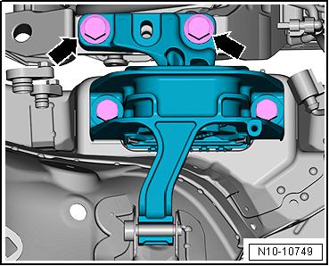
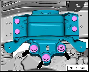
– Remove the bolts -arrows- for the engine mount (about two turns). – Remove the fan shroud. Refer to ⇒ “4.5 Fan Shroud, Removing and Installing”, page 249 .
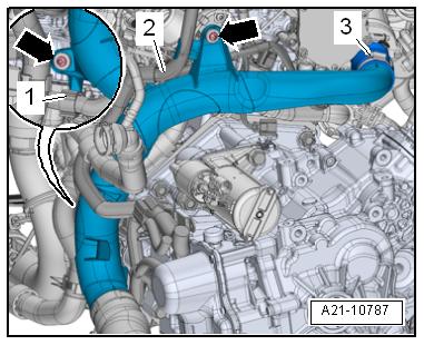
– Open the clamp -1 and 2- and remove the air duct hose. – Seal the open lines and connections with clean plugs from the
Engine Bung Set - VAS6122- .

– Free up the coolant hose -3-. – Remove the bolts -arrows-.

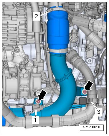
– Loosen the hose clamp -2-. Protected by copyright . Copying for piva e or commerci al p r po s e s , i n p a r t r o r in w ho le, is not permitted unless authorised by Volkswagen AG. Volkswagen AG does notguarantee or accept any liabilit y wi th res pect t o t h e c o r r e c t n e ss o f in format ion in this document. Copyright by Volkswagen AG. – Disconnect the connector -1- on the Charge Air Pressure Sen‐sor - G31- . u – Remove the right air guide pipe. – Before removing the ribbed belt, mark the running direction with chalk or a felt-tip pen for reinstallation. – Pivot the tensioner clockwise in direction of -arrow- to release the tension on the ribbed belt. t – Remove the ribbed belt from the A/C compressor ribbed belt pulley and release the tension on the tensioning device. If necessary, remove the Locking Pin - T10060A- . CAUTION Danger of frostbite from refrigerant. – Do not open the A/C system refrigerant circuit.
Golf 2015 ➤ , Golf Variant 2015 ➤ Engine Mechanical, Fuel Injection and Ignition - Edition 04.2015
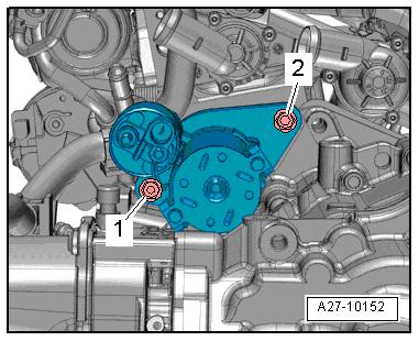
– Disconnect the connector -1- on the A/C Compressor Regu‐lator Valve - N280- .
– Remove the bolts -arrows-.
– Remove the A/C compressor from the bracket with the refrig‐erant hoses attached and tie up to the right side. While doing so, do not bend, twist or stretch the refrigerant lines and hoses. – Remove the left and right drive axles from the flange shafts.
Refer to ⇒ Suspension, Wheels, Steering; Rep. Gr. 40 ; Drive
Axle; Drive Axle, Removing and Installing . – Tie up the drive axles to the rear.
Note
Be careful not to damage the protective coating on the drive axle.

– Loosen the clamping sleeve -arrow- and push it toward the rear.
– Remove the catalytic converter with the front exhaust pipe.

Protected by copyright . Copying for pivate or commerci al pur po s e s , i n p a r t r o r in w ho le, is not permitted unless authorised by Volkswagen AG. Volkswagen AG does notguarantee or accept any liabilit y wi th res pect t o t h e c o r r e c t n e ss o f in format ion in this document. Copyright by Volkswagen AG. – Remove bolt -arrow-, push the bracket for the wiring harness aside.

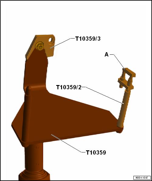
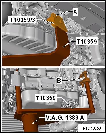
Golf 2015 ➤ , Golf Variant 2015 ➤ Protected by copyright . Copying fo pivate or commerci al pur po s e s , i n p a r t r o r in w ho le, is not permitted unless authorised by Volkswagen AG. Volkswagen AG does notguarantee or accept any liabilit y wi th res pect t o t h e c o r r e c t n e ss o f in format ion in this document. Copyright by Volkswagen AG. – Install the Adapter - T10359/3- , as shown in the illustration, on the Engine/Gearbox Jack - Engine Support - T10359A- . – Tighten Engine/Gearbox Jack - Pin - T10359/2- with support element -A- from the Transmission Support - 3282- to the en‐gine bracket. – Place the Engine/Gearbox Jack - Engine Support - T10359Ain the Engine and Gearbox Jack - VAS6931- . r – Install the Engine/Gearbox Jack - Engine Support - T10359Aon the cylinder block. Fasten the bolt -A- with the spacer sleeve on the cylinder block. Tightening specification 20 Nm. – Secure the engine with the support element -B- and lift the engine with the transmission. Engine Mechanical, Fuel Injection and Ignition - Edition 04.2015
– Remove the engine mount bolts -arrows- completely.
– Remove the transmission mount bolts -arrows- completely. – Carefully lower the engine/transmission sub-assembly in di‐rection of -arrow 1-.
– Carefully guide the engine/transmission sub-assembly for‐ward and out to the left in direction of -arrow 2-.
Protected by copyriht . Copying fo pivate or co merci al p r po s e s , i n p a r t r o r in w ho le, is not permitted unless authorised by Volkswagen AG. Volkswagen AG does notguarantee or accept any liabilit y wi th res pect t o t h e c o r r e c t n e ss o f in format ion in this document. Copyright by Volkswagen AG. 1.2 Engine and Transmission, Separating u ⇒ “1.2.1 Engine and Transmission, Separating, Vehicles with Manual Transmission”, page 19 . ⇒ “1.2.2 Engine and Transmission, Separating, Vehicles with DSG® Transmission”, page 21 . m 1.2.1 Engine and Transmission, Separating, Vehicles with Manual Transmission r Special tools and workshop equipment required ♦ Engine Support Bridge - Additional Hooks (2 pc.) - 10-222A/ 2g♦ Shop Crane - VAS6100♦ Transmission Lift Hook - T40013♦ Engine/Gearbox Jack - Engine Support - T10359ACaution
This procedure contains mandatory replaceable parts. Refer to component overview prior to starting procedure.

Mandatory Replacement Parts ♦ Bolts - Transmission Mount Golf 2015 ➤ , Golf Variant 2015 ➤ Engine Mechanical, Fuel Injection and Ignition - Edition 04.2015
Golf 2015 ➤ , Golf Variant 2015 ➤ Engine Mechanical, Fuel Injection and Ignition - Edition 04.2015
♦ Bolts - Engine to Transmission Procedure
• Engine/transmission assembly removed and secured on the
Engine/Gearbox Jack - Engine Support - T10359A- . Protected by copyright . Copying fo pivate or commerci al pur po s e s , i n p a r t r o r in w ho le, is not permitted unless authorised by Volkswagen AG. Volkswagen AG does notguarantee or accept any liabilit y wi th res pect t o t h e c o r r e c t n e ss o f in format ion in this document. Copyright by Volkswagen AG. – Free up the wire on the bracket -arrow-. – Remove the bolts -1 and 2- and then remove the starter from the transmission. – Free up the wiring harness -1 and 2- from the air guide pipe. r – Loosen the screw-type clamp -3-. – Remove the bolts -arrows- and remove the air guide pipe.

– Remove bolts -arrows- and remove the transmission support.


