
5 minute read
1.3 Cylinder Head, Removing and Installing


Golf 2015 ➤ , Golf Variant 2015 ➤ Engine Mechanical, Fuel Injection and Ignition - Edition 04.2015
6 Special Tools
Special tools and workshop equipment required ♦ Locking Pin - T10060A-

Protected by copyright . Copying for pivate or commerci al pur po s e s , i

♦ ♦ p a r t o r in w ho le, is not permitted unless authorised by Volkswagen AG. Volkswagen AG does notguarantee or accept any liabilit y wi th res pect t o t h e c o r r e c t n e ss o f Seal Installer, Intermediate Shaft - T10356/1n Counterhold - Vibration Damper - T10355♦ Assembly Tool - T10531r in format ion in this document. Copyright by Volkswagen AG.

Golf 2015 ➤ , Golf Variant 2015 ➤ Engine Mechanical, Fuel Injection and Ignition - Edition 04.2015
♦ Seal Installer - Sealing Flange Guide Sleeve - T20097-

♦ Dial Gauge - 0-10mm - VAS6079-
♦ Shop Crane - Drip Tray - VAS6208-


♦ Protected by copyright . Copying for pivate or commerci al pur po s e s , i n p a r t r o r in w ho le, is not permitted unless authorised by Volkswagen AG. Volkswagen AG does notguarantee or accept any liabilit y wi th res pect t o t h e c o r r e c t n e ss o f in format ion in this document. Copyright by Volkswagen AG. Bearing Installer - Bearing Press Piece - VW207C-
Golf 2015 ➤ , Golf Variant 2015 ➤ Engine Mechanical, Fuel Injection and Ignition - Edition 04.2015
♦ Pilot Drift - VW222A-

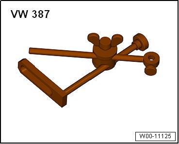
♦ Dial Gauge Holder - VW387-


♦ ♦ Protected by copyright . Copying for pivate or ommerci al pur po s e s , i n p a r t r o r in w ho le, is not permitted unless authorised by Volkswagen AG. Volkswagen AG does notguarantee or accept any liabilit y wi th res pect t o t h e c o r r e c t n e ss o f in format ion in this document. Copyright by Volkswagen AG. Internal puller, for example Puller - Kukko Internal - 14-19mm - 21/2c Counter-support for example Puller - Kukko Counterstay 22/1-
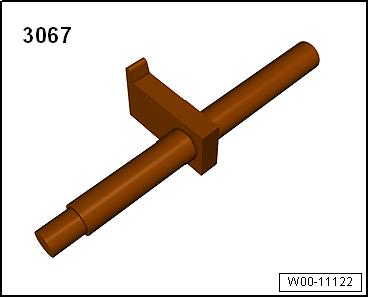
♦ Flywheel Retainer - 3067-
♦ Engine Support Bridge - Spindle - 10-222A/11♦ Plastigage® Individual components of the Assembly Tool - T10531- : ♦ Counterhold Tool - T10531/1-
♦ Tensioning Pins - T10531/2♦ Turning Over Tool - T10531/3♦ Collar Nut - T10531/4Golf 2015 ➤ , Golf Variant 2015 ➤ Engine Mechanical, Fuel Injection and Ignition - Edition 04.2015
Protected by copyright . Copying for pivate or commerci al pur po s e s , i n p a r t r o r in w ho le, is not permitted unless authorised by Volkswagen AG. Volkswagen AG does notguarantee or accept any liabilit y wi th res pect t o t h e c o r r e c t n e ss o f in format ion in this document. Copyright by Volkswagen AG.
Golf 2015 ➤ , Golf Variant 2015 ➤ Engine Mechanical, Fuel Injection and Ignition - Edition 04.2015
15 – Cylinder Head, Valvetrain
1 Cylinder Head
⇒ “1.1 Overview - Cylinder Head”, page 90 . ⇒ “1.2 Overview - Camshaft Housing”, page 93 . ⇒ “1.3 Cylinder Head, Removing and Installing”, page 94 . ⇒ “1.4 Vacuum Pump, Removing and Installing”, page 100 . ⇒ “1.5 Compression Pressure, Checking”, page 101 . 1.1 Overview - Cylinder Head
Note
♦ Replace the cylinder head bolt. ♦ Always replace self-locking nuts, bolts which have been tight‐ened to tightening specifications as well as gaskets and Orings. ♦ The plastic protectors installed to protect the open valves must only be removed immediately before mounting the cylinder head. ♦ The engine oil and the coolant must be changed if the cylinder head or the cylinder head gasket are being replaced.
Protected by copyright . Copying for pivate or commerci al pur po s e s , i n p a r t r o r in w ho le, is not permitted unless authorised by Volkswagen AG. Volkswagen AG does notguarantee or accept any liabilit y wi th res pect t o t h e c o r r e c t n e ss o f in format ion in this document. Copyright by Volkswagen AG.
Golf 2015 ➤ , Golf Variant 2015 ➤ Engine Mechanical, Fuel Injection and Ignition - Edition 04.2015
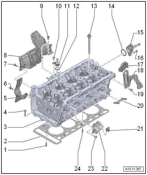
1 - Alignment Pin 2 - Cylinder Head Gasket ❑ Replace after removing ❑ Installed position: the part number faces the cylinder head 3 - Cylinder Head ❑ Removing and instal‐ling. Refer to ⇒ “1.3 Cylinder Head, Removing and Instal‐ling”, page 94 . ❑ Check for distortion. Re‐fer to ⇒ Fig. ““Checking Cylin‐der Head for Distor‐tion”“ , page 93 4 - Bolt ❑ 4 Nm + 90° ❑ Follow the procedure when loosening. Refer to ⇒ Fig. ““Loosening Cyl‐inder Head”“ , page 92 ❑ Follow the procedure when tightening. Refer to ⇒ Fig. ““Cylinder Head Tightening Sequence”“ , page 92 ❑ Replace after removing Protected by copyright . Copying fo pivate or commerci al pur po s e , i n p a r t r o r in w ho le, is not permitted unless authorised by Volkswagen AG. Volkswagen AG does notguarantee or accept any liabilit y wi th res pect t o t h e c o r r e c t n e ss o f in format ion in this document. Copyright by Volkswagen AG. 5 - Heat Shield 6 - Bolt ❑ 9 Nm 7 - Bolt ❑ 9 Nm 8 - Heat Shield 9 - Bolt ❑ 9 Nm 10 - Bolt ❑ 9 Nm s 11 - Connection ❑ For coolant hose r 12 - O-Ring ❑ Coat with coolant ❑ Replace after removing 13 - Cylinder Head Bolt ❑ Follow the procedure when loosening. Refer to ⇒ Fig. ““Loosening Cylinder Head”“ , page 92 ❑ Follow the procedure when tightening. Refer to ⇒ Fig. ““Cylinder Head Tightening Sequence”“ , page 92 ❑ Replace after removing 1. Cylinder Head 91


