3 minute read
1.5 Oil Pump, Removing and Installing


Golf 2015 ➤ , Golf Variant 2015 ➤ Engine Mechanical, Fuel Injection and Ignition - Edition 04.2015
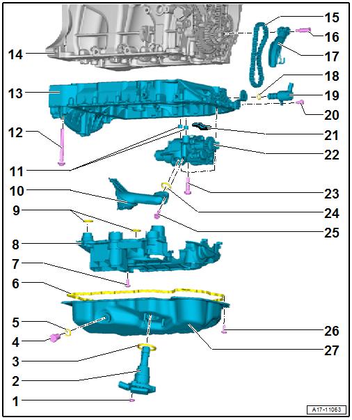
1 - Nut ❑ 9 Nm
2 - Oil Level Thermal Sensor G266❑ Removing and instal‐ling. Refer to ⇒ “1.6 Oil Level Ther‐mal Sensor G266 , Re‐moving and Installing”, page 190 . 3 - 0-Ring ❑ Replace after removing ❑ Coat with engine oil 4 - Oil Drain Plug/Plug ❑ Sheet metal oil pan: 30 Nm ❑ Plastic oil pan: turn us‐ing the Oil Drain Plug Assembly Tool T10549- until it stops 5 - Gasket/O-Ring ❑ Replace the gasket after removal ❑ Replace the O-ring if there are leaks
Protected by copyright . Copying fo pivate or commerci al pur po s e s , i n p a r t r o r in w ho le, is not permitted unless authorised by Volkswagen AG. Volkswagen AG does notguarantee or accept any liabilit y wi th res pect t o t h e c o r r e c t n e ss o f in format ion in this document. Copyright by Volkswagen AG. r 6 - Seal/Liquid Sealant ❑ Refer to parts catalog 7 - Bolt ❑ 4 Nm + 45° ❑ Replace after removing ❑ For the oil baffle and oil intake pipe 8 - Oil Baffle ❑ There are plastic ribs on the oil baffle that deform permanently when tightening the oil pan lower section. The plastic ribs ensure the oil baffle has no play and does not rattle. Because of this, always replace the oil baffle.
9 - O-Ring ❑ Replace after removing ❑ Coat with engine oil 10 - Oil Intake Pipe ❑ Clean the screen if there are debris
11 - Centering Bracket 12 - Bolt ❑ Replace after removing ❑ Coat with engine oil 13 - Oil Pan Upper Section ❑ Removing and installing. Refer to ⇒ “1.4 Oil Pan Upper Section, Removing and Installing”, page 185 . ❑ Tightening sequence. Refer to ⇒ Fig. ““Oil Pan Upper Section - Tightening Sequence”“ , page 181 . 14 - Cylinder Block 15 - Oil Pump Drive Chain ❑ Mark direction of rotation before removing
Golf 2015 ➤ , Golf Variant 2015 ➤ Engine Mechanical, Fuel Injection and Ignition - Edition 04.2015
16 - Bolt ❑ 9 Nm
17 - Chain Tensioner
18 - O-Ring ❑ Replace after removing ❑ Coat with engine oil 19 - Oil Pressure Regulation Valve - N428❑ Removing and installing. Refer to ⇒ “4.8 Oil Pressure Regulation Valve N428 , Removing and Installing”, page 206 . 20 - Bolt ❑ Replace after removing ❑ Tightening sequence. Refer to ⇒ Fig. ““Oil Pan Upper Section - Tightening Sequence”“ , page 181 21 - Oil Screen
22 - Oil Pump ❑ Removing and installing. Refer to ⇒ “1.5 Oil Pump, Removing and Installing”, page 188 . 23 - Oil Pump Bolt ❑ 8 Nm +90° ❑ Replace after removing 24 - O-Ring ❑ Replace after removing ❑ Coat with engine oil 25 - Oil Intake Pipe Bolt ❑ 4 Nm +45° ❑ Replace after removing 26 - Oil Pan Bolt ❑ Replace after removing ❑ Tightening sequence. Refer to ⇒ “1.3 Oil Pan Lower Section, Removing and Installing”, page 182 . 27 - Oil Pan Lower Section ❑ Metal or plastic u ❑ Removing and installing. Refer to ⇒ “1.3 Oil Pan Lower Section, Removing and Installing”, page 182 .
m Oil Pan Upper Section - Tightening Sequence

Protected by coyright . Copyi g for pi ate or co merci al p r po s e s , i n p a r t r o r in w ho le, is not permitted unless authorised by Volkswagen AG. Volkswagen AG does notguarantee or accept any liabilit y wi th res pect t o t h e c o r r e c t n e ss o f in format ion in this document. Copyright by Volkswagen AG. v Note n Replace the bolts that were tightened with an additional turn. p – Tighten the bolts -1 through 14- in the sequence shown. Step Bolts Tightening Sequence and Tightening Specification 1. -1- to -14- 8 Nm
2. -1- and -2- 180° additional turn
3. -3- to -9- 45° additional turn
4. -10- 180° additional turn
5. -11- to -14- 90° additional turn


