
36 minute read
4.2 Camshaft, Removing and Installing


Golf 2015 ➤ , Golf Variant 2015 ➤ Engine Mechanical, Fuel Injection and Ignition - Edition 04.2015
– Install the chain tensioner -1- and tighten the bolts -arrows-.
– Install the chain tensioner -2-. The wire clip -arrow- must come in to contact with the oil pan upper section opening. Tighten the bolt -1- and remove the Locking Pin (3 pc.) - T40011- .
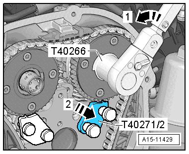
– Turn the intake camshaft in the direction of the arrow -1- using the Adapter - T40266- until the Camshaft Lock - T40271/2-2- can be pushed out of the chain sprocket splines. Release the camshaft.
– Remove the Camshaft Lock - Component 1 - T40271/1- and
Camshaft Lock - Component 2 - T40271/2- .


Protectd by copyright . Copying for pivate or commerci al pur po s e s , i n p a r t r o r in w ho le, is not permitted unless authorised by Volkswagen AG. Volkswagen AG does notguarantee or accept any liabilit y wi th res pect t o t h e c o r r e c t n e ss o f in format ion in this document. Copyright by Volkswagen AG. – Check the adjustment. The painted chain links -arrows- must line up with the markings on the chain sprockets. e128 Rep. Gr.15 - Cylinder Head, Valvetrain
Golf 2015 ➤ , Golf Variant 2015 ➤ Engine Mechanical, Fuel Injection and Ignition - Edition 04.2015
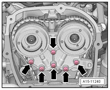
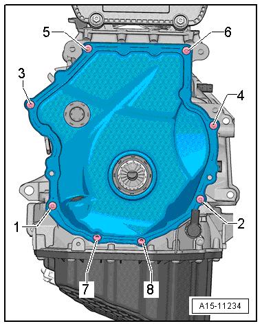
– Install the bolts -arrows- and tighten them. Tightening specifi‐cation. Refer to -item 4- ⇒ Item 4 (page 91) .
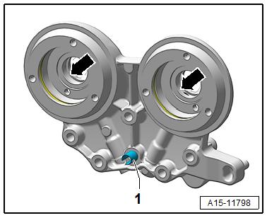
– Lubricate the holes -arrows- with engine oil.
Note

Protectd by copyright . Copying for pivate or commerci al pur po s e s , i n p a r t r o r in w ho le, is not permitted unless authorised by Volkswagen AG. Volkswagen AG does notguarantee or accept any liabilit y wi th res pect t o t h e c o r r e c t n e ss o f in format ion in this document. Copyright by Volkswagen AG. Adapter sleeve -1- is not present on every bearing bracket. – Attach the bearing mount. Do not tilt it when doing this. Handtighten the bolts -arrows-. e – Remove the Tensioner Locking Tool - T40267- . – Tighten the bearing bracket bolts -item 5⇒ Item 5 (page 115) . – Install the pilot valves -item 6- ⇒ Item 7 (page 115) . – Let the engine turn a second time in the direction of engine rotation. Note
Due to the ratio, the painted chain links no longer match up after the engine has been turned.
Protected by copyright . Copying fo pivate or co merci al pur po s e s , i n p a r t r o r in w ho le, is not permitted unless authorised by Volkswagen AG. Volkswagen AG does notguarantee or accept any liabilit y wi th res pect t o t h e c o r r e c t n e ss o f in format ion in this document. Copyright by Volkswagen AG. – Remove the turning over tool and install the lower timing chain cover. Refer to ⇒ page 109 . Note Tighten the bolts -1 and 4- with an additional turn after installing the vibration damper. The bolts must be removed again to install the vibration damper. m – Install the vibration damper. Refer to ⇒ “1.4 Vibration Damper, Removing and Installing”, page 47 . – Install the upper timing chain cover. Refer to ⇒ “2.2.1 Upper Timing Chain Cover, Removing and Installing”, page 106 . – Install the ribbed belt tensioning damper. Refer to ⇒ “1.3 Ribbed Belt Tensioner, Removing and Installing”, page 47 . r – Install the ribbed belt. Refer to ⇒ “1.2 Ribbed Belt, Removing and Installing”, page 46 . The rest of the installation is performed in reverse order of re‐moval, noting the following: – After performing work on the chain drive the adaptation value in the Engine Control Module (ECM) must be adapted. To do this turn on the ignition and select the following menu items on the Vehicle Diagnostic Tester : Golf 2015 ➤ , Golf Variant 2015 ➤ Engine Mechanical, Fuel Injection and Ignition - Edition 04.2015
♦ 01 - Engine Electronics
♦ Guided Functions
♦ 01 - Adaptation After Repair Work On the Chain
Drive
Tightening Specifications ♦ Refer to ⇒ “3.1 Overview - Camshaft Timing Chain”, page 114 . ♦ Refer to ⇒ “3.2 Overview - Balance Shaft Drive Chain”, page 116 . ♦ Refer to ⇒ Body Exterior; Rep. Gr. 66 ; Noise Insulation;
Overview - Noise Insulation .
The procedure “Balance shaft drive chain removing and installing” is in the “Camshaft timing chain removing and installing” proce‐dure. Refer to ⇒ “3.3 Camshaft Timing Chain, Removing and Installing”, page 118 . 3.5 Chain Length, Checking
Caution
This procedure contains mandatory replaceable parts. Refer to component overview prior to starting procedure.
Mandatory Replacement Parts ♦ Plug - Lower Timing Chain Cover
Golf 2015 ➤ , Golf Variant 2015 ➤ Engine Mechanical, Fuel Injection and Ignition - Edition 04.2015
Note
If due to complaints (for example noises) an elongated camshaft timing chain is suspected, the chain length can be checked as described as follows.
– Remove the plug -arrow-. The plugs must be replaced.
– Turn the vibration damper in direction of engine rotation until the chain tensioner piston is maximally driven out in direction of -arrow-.
– Count the visible piston threads.
Note
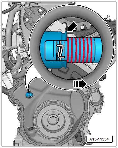

Protected by copyright . Copying fo pivate or commer i al pur po s e s , i n p a r t r o r in w ho le, is not permitted unless authorised by Volkswagen AG. Volkswagen AG does notguarantee or accept any liabilit y wi th res pect t o t h e c o r r e c t n e ss o f in format ion in this document. Copyright by Volkswagen AG. c The visible threads are all of the threads that are located to the right of the chain tensioner housing -arrow-. r ♦ If six or fewer threads are visible: the camshaft timing chain does not need to be replaced. ♦ If seven or more threads are visible: the camshaft timing chain must be replaced. Refer to ⇒ “3.3 Camshaft Timing Chain, Removing and Installing”, page 118 . 3.6 Valve Timing, Checking Special tools and workshop equipment required ♦ Dial Gauge Set - VAS6341♦ Dial Gauge Adapter - T10170A– Remove timing chain upper cover. Refer to ⇒ “2.2.1 Upper Timing Chain Cover, Removing and Installing”, page 106 . – Remove the noise insulation. Refer to ⇒ Body Exterior; Rep.
Gr. 66 ; Noise Insulation; Overview - Noise Insulation .
Golf 2015 ➤ , Golf Variant 2015 ➤ Engine Mechanical, Fuel Injection and Ignition - Edition 04.2015
– Turn the crankshaft with the socket SW 24 on the vibration damper in the direction of the engine rotation until the mark‐ings -arrows- are almost on top. – Remove the spark plug from cylinder 1.
– Install the Dial Gauge Adapter - T10170/A- all the way into the spark plug thread. – Insert the Dial Gauge - 0-10mm - VAS6341- using the Exten‐sion - T10170A/1- until stop and secure with the locking nut -arrow-.
– Turn the crankshaft slowly to maximum dial reading in the di‐rection of the engine rotation. When the maximum dial reading is reached (Bottom Dead Center (BDC) of the meter) position the piston at »Top Dead Center (TDC)«.
Note
♦ Use a ratchet with a 24 mm socket to turn the vibration damper. ♦ If the crankshaft was turned past “TDC”, turn the crankshaft two more turns in the direction of the engine rotation. Do not turn the engine in the opposite direction of the engine rotation.


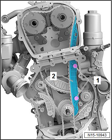
• The notch on the vibration damper must line up with the arrow marking on the timing chain lower cover -arrow-. Protected by copyright . Copying for pivate or commerci al pur po s e s , i n p a r t r o r in w ho le, is not permitted unless authorised by Volkswagen AG. Volkswagen AG does notguarantee or accept any liabilit y wi th res pect t o t h e c o r r e c t n e ss o f in format ion in this document. Copyright by Volkswagen AG. • The markings -1- on the camshaft chain sprockets must be opposite the markings -2 and 3- on the cylinder head. 132 Rep. Gr.15 - Cylinder Head, Valvetrain
Golf 2015 ➤ , Golf Variant 2015 ➤ Engine Mechanical, Fuel Injection and Ignition - Edition 04.2015
4 Valvetrain
⇒ “4.1 Overview - Valvetrain”, page 133 ⇒ “4.2 Camshaft, Removing and Installing”, page 136 ⇒ “4.3 Camshaft Adjustment Valve 1 N205 , Removing and In‐stalling”, page 160 ⇒ “4.4 Camshaft Adjustment Valve 1 N205 and Exhaust Cam‐shaft Adjustment Valve 1 N318 , Removing and Installing”, page 161
⇒ “4.5 Sliding Bar Ball, Installing”, page 162 ⇒ “4.6 Valve Stem Seals, Removing and Installing”, page 163 4.1 Overview - Valvetrain
Note
♦ The cylinder head and the cylinder head cover must be re‐placed together. ♦ Do not start the engine for approximately 30 minutes after in‐stalling the camshafts. The hydraulic equalization elements must seat themselves (otherwise the valves will crash into the pistons). ♦ After working on the valvetrain and lifters, carefully rotate the crankshaft by hand at least two full revolutions before starting ♦ ♦ ♦ ♦ ♦ Protected by copyright . Copying for pivate or commerci al pur po s e s , i n p a r t r o r in w ho le, is not permitted unless authorised by Volkswagen AG. Volkswagen AG does notguarantee or accept any liabilit y wi th res pect t o t h e c o r r e c t n e ss o f in format ion in this document. Copyright by Volkswagen AG. to be sure that valves do not strike the pistons. Replace the gaskets and seals. After performing work on the chain drive the adaptation value in the Engine Control Module (ECM) must be adapted. To do this turn on the ignition and select the following menu items on the Vehicle Diagnostic Tester : 01 - Engine Electronics Guided Functions 01 - Adaptation After Repair Work On the Chain Drive
Golf 2015 ➤ , Golf Variant 2015 ➤ Engine Mechanical, Fuel Injection and Ignition - Edition 04.2015
1 - Exhaust Valve ❑ Do not rework, only lap‐ping is permitted ❑ Valve dimensions. Re‐fer to ⇒ “5.3 Valve Dimen‐sions”, page 170 . ❑ Valve guides, checking. Refer to ⇒ “5.1 Valve Guides, Checking”, page 170 . 2 - Cylinder Head 3 - Valve Stem Seal ❑ Replacing. Refer to ⇒ “4.6 Valve Stem Seals, Removing and Installing”, page 163 . 4 - Valve Spring 5 - Valve Spring Retainer 6 - Valve Retainers

7 - Hydraulic Adjusting Ele‐ment ❑ Do not interchange ❑ Lubricate contact sur‐face
8 - Clip ❑ For hydraulic adjuster 9 - Roller Rocker Lever Protected by copyriht . Copying for pivate or commerci al pur po s e s , i n p a r t r o r in w ho le, is not permitted unless authorised by Volkswagen AG. Volkswagen AG does notguarantee or accept any liabilit y wi th res pect t o t h e c o r r e c t n e ss o f in format ion in this document. Copyright by Volkswagen AG. g ❑ Removing and instal‐ling. Refer to ⇒ “4.2 Camshaft, Re‐moving and Installing”, page 136 . ❑ Mark the installed position for installation later ❑ Check roller for easy movement ❑ Lubricate the running surfaces before installing 10 - Exhaust Camshaft ❑ Removing and installing. Refer to ⇒ “4.2 Camshaft, Removing and Installing”, page 136 . ❑ Check radial clearance using Plastigage® (roller rocker lever removed) ❑ Radial clearance: 0.024 to 0.066 mm ❑ Run-out: maximum 0.04 mm
11 - Spring ❑ No replacement part 12 - Ball ❑ For sliding bar ❑ Installing. Refer to ⇒ “4.5 Sliding Bar Ball, Installing”, page 162 . 13 - Cylinder Head Cover ❑ With integrated camshaft bearings ❑ Clean sealing surface, reworking is not permitted. ❑ Remove old sealant residue.
Golf 2015 ➤ , Golf Variant 2015 ➤ Engine Mechanical, Fuel Injection and Ignition - Edition 04.2015

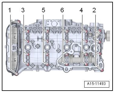
14 - Bolt ❑ Replace after removing Protected by copyright . Copying for pivate or co merci al pur po e s , i n p a r t r o r in w ho le, is not permitted unless authorised by Volkswagen AG. Volkswagen AG does notguarantee or accept any liabilit y wi th res pect t o t h e c o r r e c t n e ss o f in format ion in this document. Copyright by Volkswagen AG. ❑ Loosening. Refer to ⇒ Fig. ““Loosening the Cylinder Head Cover”“ , page 135 ❑ Tightening sequence. Refer to ⇒ Fig. ““Cylinder Head Cover Tightening Sequence”“ , page 135 15 - Intake Camshaft ❑ Removing and installing. Refer to ⇒ “4.2 Camshaft, Removing and Installing”, page 136 . ❑ Check radial clearance using Plastigage® (roller rocker lever removed) ❑ Radial clearance: 0.024 to 0.066 mm ❑ Run-out: maximum 0.04 mm s 16 - Alignment Pins 17 - Alignment Pins 18 - Intake Valve ❑ Do not rework, only lapping is permitted ❑ Valve dimensions. Refer to ⇒ “5.3 Valve Dimensions”, page 170 . ❑ Valve guides, checking. Refer to ⇒ “5.1 Valve Guides, Checking”, page 170 . m Loosening the Cylinder Head Cover – Loosen the cylinder head cover in the order -1 through 6-. Cylinder Head Cover Tightening Sequence – Replace the bolts after removing them. Step Bolts Tightening Specification/Additional Turn 1. -1- through -6- Install hand-tight in several stages 2. -1- through -6- 8 Nm 3. -1- through -6- Turn an additional 90°. Note
Pay attention that the cylinder head cover is not tilted.

Golf 2015 ➤ , Golf Variant 2015 ➤ Engine Mechanical, Fuel Injection and Ignition - Edition 04.2015
ht . Copying for pivate or commerci al pur po s e s , i Protected by copyri
4.2 Camshaft, Removing and Installing p a r t r o r in w ho le, is not permitted unless authorised by Volkswagen AG. Volkswagen AG does notguarantee or accept any liabilit y wi th res pect t o t h e c o r r e c t n e ss o f in format ion in this document. Copyright by Volkswagen AG. ⇒ “4.2.1 Camshaft, Removing and installing. Engine Codes CXBA, CNSA, CXBB, and CNSB”, page 136 . ⇒ “4.2.2 Camshaft, Removing and Installing, Engine Codes CNTA, CXCA, CXCB”, page 148 . 4.2.1 Camshaft, Removing and installing. En‐gine Codes CXBA, CNSA, CXBB, and CNSB n Special tools and workshop equipment required ♦ Central Valve Assembly Tool - T10352♦ Counterhold - Vibration Damper - T10355♦ Chain Tensioner Lever - T40243♦ Tensioner Locking Tool - T40267♦ Camshaft Locks - T40271♦ Adapter - T40266♦ Sealant - D 154 103 A1Removing Note g♦ The sealing surfaces of the lower cylinder head cover and on the upper cylinder head must not be reworked. ♦ The camshaft bearings are integrated in the cylinder head or cylinder head cover. The tension must be released from the camshaft timing chain before removing the cylinder head cov‐er. ♦ When installing, secure all cable ties back to same positions.
– Remove the air filter housing. Refer to ⇒ “3.2 Air Filter Housing, Removing and Installing”, page 294 . – Remove the upper coolant pipe. Refer to ⇒ “3.3 Upper Coolant Pipes, Removing and Installing”, page 242 . – Remove the ignition coils. Refer to ⇒ “1.3 Ignition Coils with Power Output Stages, Removing and
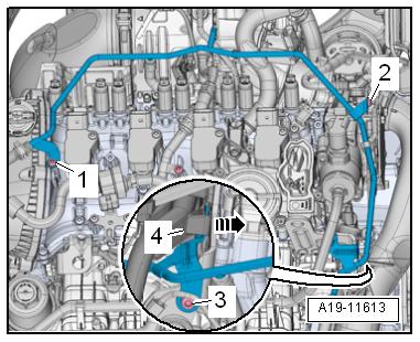
Installing”, page 357 . – Free up the connector from the clip -4- and pivot it forward. – Release the retainers -arrow-, remove the wiring duct upward from the bracket and move it towards the front.
Golf 2015 ➤ , Golf Variant 2015 ➤ Engine Mechanical, Fuel Injection and Ignition - Edition 04.2015
– Remove bolts -1, 2 and 3-. Carefully swing coolant line back‐ward slightly.
NOTICE
Risk of destroying the coolant pipes through deformation. – Never change the coolant pipe bent shape.

Protected by copyright . Copying fo pivate or co merci al pur po s e s , i n p a r t r o r in w ho le, is not permitted unless authorised by Volkswagen AG. Volkswagen AG does notguarantee or accept any liabilit y wi th res pect t o t h e c o r r e c t n e ss o f in format ion in this document. Copyright by Volkswagen AG. – Disconnect the connector -1- from the EVAP Canister Purge Regulator Valve 1 - N80- . – Press the release button on the crankcase ventilation hose -2- and remove the hose. – Remove the bolts -arrows- and the crankcase ventilation. m – Remove the high pressure pump. Refer to ⇒ “7.2 High Pressure Pump, Removing and Installing”, page 328 . – Remove the vacuum pump. Refer to ⇒ “1.4 Vacuum Pump, Removing and Installing”, page 100 . – Support the engine in its installed position. Refer to ⇒ “2.5 Engine, Supporting in Installed Position”, page 33 . – Remove the engine bracket. Refer to ⇒ “2.2 Engine Mount, Removing and Installing”, page 30 . – Remove the noise insulation. Refer to ⇒ Body Exterior; Rep. Gr. 66 ; Noise Insulation; Overview - Noise Insulation . r– Remove the right wheel housing liner front section. Refer to ⇒ Body Exterior; Rep. Gr. 66 ; Wheel Housing Liner; Front Wheel Housing Liner, Removing and Installing . – Remove engine support. Refer to ⇒ “1.6 Engine Support, Removing and Installing”, page 55 . – Remove timing chain upper cover. Refer to ⇒ “2.2.1 Upper Timing Chain Cover, Removing and Installing”, page 106 . – Turn the vibration damper with the Counterhold - Vibration
Damper - T10355- to the “TDC point”. • The markings -1- on the camshaft chain sprockets must be opposite the markings -2 and 3-. • The notch on the vibration damper and the marking on the lower cover for timing chain -arrow- must be opposite one an‐other.
Golf 2015 ➤ , Golf Variant 2015 ➤ Engine Mechanical, Fuel Injection and Ignition - Edition 04.2015
– Remove the lower timing chain cover. Refer to ⇒ “2.2.2 Lower Timing Chain Cover, Removing and Installing”, page 108 .
Note
The pilot valve has left-hand threads.

Protected by copyright . Co ying for pivate or commerci al pur po s e s , i n p a r t r o r in w ho le, is not permitted unless authorised by Volkswagen AG. Volkswagen AG does notguarantee or accept any liabilit y wi th res pect t o t h e c o r r e c t n e ss o f in format ion in this document. Copyright by Volkswagen AG. – Remove the left and right pilot valves using the Assembly Tool - T10352/2- in the direction of the -arrow-. p – Remove the bolts -arrows- and remove the bearing bracket.
– Remove the bolts -arrows-.
Golf 2015 ➤ , Golf Variant 2015 ➤ Engine Mechanical, Fuel Injection and Ignition - Edition 04.2015
– Install the Chain Tensioner Lever - T40243- -arrows-.
– Press the chain tensioner locking ring -1- together and hold it. – Slowly press and hold the Chain Tensioner Lever - T40243in the direction of -arrow-.
– Secure the chain tensioner with the Tensioner Locking Tool -
T40267- .
– Remove the Chain Tensioner Lever - T40243- .


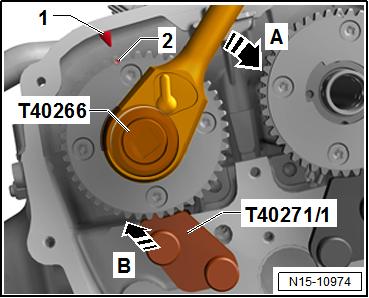
Protected by copyright . Copying for pivate or commer i al pur po e s , i n p a r t r o r in w ho le, is not permitted unless authorised by Volkswagen AG. Volkswagen AG does notguarantee or accept any liabilit y wi th res pect t o t h e c o r r e c t n e ss o f in format ion in this document. Copyright by Volkswagen AG. s – Bolt the Camshaft Lock - Component 2 - T40271/2- to the cyl‐inder head and slide into the splines on the chain sprocket in the direction of -arrow 2-. Rotate the intake camshaft with the Adapter - T40266- -1- if necessary. – Install the Camshaft Lock - Component 1 - T40271/1- on the cylinder head. For the following steps a second technician is necessity. – Hold the exhaust camshaft with the Adapter - T40266- in the direction of the -arrow A-. Remove the bolt -1- and guide the tensioning rail -2- downward. Turn the camshaft clockwise -A- until the Camshaft Lock - Component 1 - T40271/1- in the direction of -arrow B- can be pushed in the chain sprocket splines -arrow C-. c – Check the installation position -arrow C- of the Camshaft Lock - Component 1 - T40271/1- .
Golf 2015 ➤ , Golf Variant 2015 ➤ Engine Mechanical, Fuel Injection and Ignition - Edition 04.2015
– Remove the guide rail -1- by unlocking the latch -arrow- with a screwdriver and pushing the guide rail forward.

– Press the oil pump chain tensioner bracket in direction of -arrow- and lock with Locking Pin (3 pc.) - T40011- . – Remove the bolt -1- and remove the chain tensioner.
Protected by copyright . Copying fo pivate or commerci al pur po s e s , i n p a r t r o r in w ho le, is not permitted unless authorised by Volkswagen AG. Volkswagen AG does notguarantee or accept any liabilit y wi th res pect t o t h e c o r r e c t n e ss o f in format ion in this document. Copyright by Volkswagen AG. – Remove the bolts -1- and remove the glide rail -2-. – Remove the camshaft timing chain from the camshaft bearing and guide downward. r – Install the Turning Over Tool - T10531/3- . In the “TDC point” the flat area -1- points upward. Install the Knurled Nut T10531/4- . Turn the crankshaft with a 32 mm open end wrench counter-clockwise out of Top Dead Center (TDC).


Golf 2015 ➤ , Golf Variant 2015 ➤ Engine Mechanical, Fuel Injection and Ignition - Edition 04.2015
– Turn the intake camshaft in the direction of the -arrow 1- using the Adapter - T40266- . Slide the Camshaft Lock - T40271/2out of the chain sprocket splines -2- and bring the camshaft into the rest position.
– Turn the exhaust camshaft in the direction of the -arrow 1- us‐ing the Adapter - T40266- . Slide the Camshaft Lock -
T40271/1- -2- out of the chain sprocket splines and bring the camshaft into the rest position. – Remove the cylinder head cover bolts in -1 to 6- sequence. – Remove the cylinder head cover.
– Remove the camshaft and cover the open engine compo‐nents.
Camshafts, Installing
Note


Protected by opyright . Co ying for pivate or co merci al pur po s e s , i n p a r t r o r in w ho le, is not permitted unless authorised by Volkswagen AG. Volkswagen AG does notguarantee or accept any liabilit y wi th res pect t o t h e c o r r e c t n e ss o f in format ion in this document. Copyright by Volkswagen AG. m♦ Sealing surfaces must be completely free of oil and grease. ♦ Pay attention that all roller rocker levers rest on the valve stem ends. p – If the crankshaft was turned in the meanwhile: bring the piston for cylinder 1 to TDC and then turn the crankshaft back just a little. c – Remove any sealant residue from the groove on the cylinder head cover as well as on the sealing surfaces. – Clean the sealing surfaces. They must be free of oil and grease. – Lubricate the running surfaces of both camshafts.
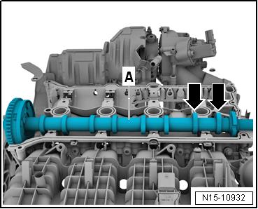
– Place the intake camshaft -A- in the cylinder head. Turn the cam lobes from cylinder 4 -arrows- upward.
Golf 2015 ➤ , Golf Variant 2015 ➤ Engine Mechanical, Fuel Injection and Ignition - Edition 04.2015
– Insert the exhaust camshaft -1- in the cylinder head cover.
Turn the cam lobes from cylinder 4 -arrows- upward.


ht . Copying for pivate or commerci al pur po s e s , i Protected by copyri
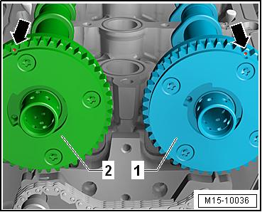
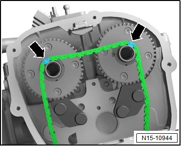
p a r t o r in w ho le, is not permitted unless authorised by Volkswagen AG. Volkswagen AG does notguarantee or accept any liabilit y wi th res pect t o t h e c o r r e c t n e ss o f – Turn the intake camshaft -1- and the exhaust camshaft -2- until the markings -arrows- are in the -position shown-. n – The cams -arrows- the intake camshaft -1- and the exhaust camshaft -2- point upward as illustrated. r g – Apply the sealant on the clean sealing surface of the cylinder head cover as illustrated -arrows-. ♦ Sealant bead thickness: 2 to 3 mm. in format ion in this document. Copyright by Volkswagen AG. – Mount the cylinder head cover on the cylinder head.

Golf 2015 ➤ , Golf Variant 2015 ➤ Engine Mechanical, Fuel Injection and Ignition - Edition 04.2015


– Lightly push on the cylinder head cover by hand and while Protected by copyriht . Copying for pivate or commerci al pur po e s , i n p a r t r o r in w ho le, is not permitted unless authorised by Volkswagen AG. Volkswagen AG does notguarantee or accept any liabilit y wi th res pect t o t h e c o r r e c t n e ss o f in format ion in this document. Copyright by Volkswagen AG. doing this turn the camshaft slightly until the cylinder head cover lays free of tension on the cylinder head. – Replace the cylinder head cover bolts. – Tighten the bolts in several steps, tightening sequence. Refer to ⇒ Fig. ““Cylinder Head Cover Tightening Sequence”“ , page 135 . Note Pay attention that the cylinder head cover is not tilted. s – Turn the intake camshaft with the Adapter - T40266- in the direction of -arrow A- until the markings -1 and 2- align. Push the Camshaft Lock - Component 2 - T40271/2- in the chain sprocket splines in direction of -arrow B-. g – Turn the exhaust camshaft with the Adapter - T40266- in the direction of -arrow A- until the markings -1 and 2- align. Push the Camshaft Lock - Component 1 - T40271/1- in the chain sprocket splines in direction of -arrow B-. The mark -2- is offset slightly to the right.
– Turn the crankshaft on the hex fitting to the “Top Dead Center (TDC) point”. In the “TDC point” flat area -1- is upward.
Golf 2015 ➤ , Golf Variant 2015 ➤ Engine Mechanical, Fuel Injection and Ignition - Edition 04.2015
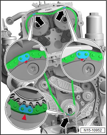
Install the Camshaft Timing Chain – Engage the camshaft timing chain with the painted links Protected by copyright . Copying for pivate or commerci al pur po s e s , i n p a r t r o r in w ho le, is not permitted unless authorised by Volkswagen AG. Volkswagen AG does notguarantee or accept any liabilit y wi th res pect t o t h e c o r r e c t n e ss o f in format ion in this document. Copyright by Volkswagen AG. -arrows- on the camshaft pins. – Place the camshaft timing chain on the intake camshaft, ex‐haust camshaft and the crankshaft. Position the painted chain links -arrows- on the markings on the chain sprockets. – Install the guide rail -2- and tighten the bolts -1-.
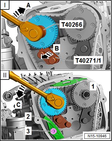
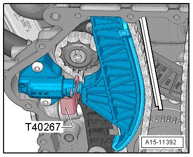
Protected by copyright . Copying fo pivate or co merci al pur po s e s , i n p a r t r o r in w ho le, is not permitted unless authorised by Volkswagen AG. Volkswagen AG does notguarantee or accept any liabilit y wi th res pect t o t h e c o r r e c t n e ss o f in format ion in this document. Copyright by Volkswagen AG. – Install the upper glide rail -1-. m For the following steps a second technician is necessity. I - Turn the exhaust camshaft with the Adapter - T40266- slightly in the direction of -arrow A- and push the Camshaft Lock - Com‐ponent 1 - T40271/1- from the camshaft splines in direction of -arrow B-. r II - Release the camshaft in the direction -arrow C-, until the timing chain touches the glide rail -1-. Hold the camshaft in this position, install the tensioning rail -2- and tighten the bolts -3-. Release the camshaft.
Golf 2015 ➤ , Golf Variant 2015 ➤ Engine Mechanical, Fuel Injection and Ignition - Edition 04.2015
– Turn the intake camshaft with the Adapter - T40266- in the direction of -arrow 1- until the Camshaft Lock - Component 2 - T40271/2- can be pushed out of the chain sprocket splines in the direction of -arrow 2-. Release the camshaft.
– Remove the Camshaft Lock - Component 1 - T40271/1- and
Camshaft Lock - Component 2 - T40271/2- .
– Install the bolts -arrows- and tighten them. Tightening specifi‐cation. Refer to -item 4- ⇒ Item 4 (page 91) .
Golf 2015 ➤ , Golf Variant 2015 ➤ Engine Mechanical, Fuel Injection and Ignition - Edition 04.2015
– Attach the bearing mount. Do not tilt it when doing this. Handtighten the bolts -arrows-.
– Remove the Tensioner Locking Tool - T40267- .
– Tighten the bearing bracket bolts -arrows-. Tightening speci‐Protected by copyright . Copying for pivate or commerci al pur po s e s , i n p a r t r o r in w ho le, is not permitted unless authorised by Volkswagen AG. Volkswagen AG does notguarantee or accept any liabilit y wi th res pect t o t h e c o r r e c t n e ss o f in format ion in this document. Copyright by Volkswagen AG. fication -item 5- ⇒ Item 5 (page 115) . – Install the chain tensioner -2-. The wire clip must come in to contact with the oil pan upper section opening -arrow-. Tighten the bolt -1- and remove the Locking Pin (3 pc.) - T40011- .
Golf 2015 ➤ , Golf Variant 2015 ➤ Engine Mechanical, Fuel Injection and Ignition - Edition 04.2015
– Check the adjustment. The painted chain links -arrows- must line up with the markings on the chain sprockets. – Install the pilot valves -item 7- ⇒ Item 7 (page 115) . – Let the engine turn a second time in the direction of engine rotation.
Note
Due to the ratio, the painted chain links no longer match up after the engine has been turned.

Protected by copyright . Copying for pivate or commerci al pur po s e s , i n p a r t r o r in w ho le, is not permitted unless authorised by Volkswagen AG. Volkswagen AG does notguarantee or accept any liabilit y wi th res pect t o t h e c o r r e c t n e ss o f in format ion in this document. Copyright by Volkswagen AG. – Remove the Knurled Nut - T10531/4- and remove the Turning Over Tool - T10531/3- . – Install the lower timing chain cover. Refer to ⇒ page 109 .
Golf 2015 ➤ , Golf Variant 2015 ➤ Engine Mechanical, Fuel Injection and Ignition - Edition 04.2015
Note
Tighten the bolts -1 and 4- with an additional turn after installing the vibration damper. The bolts must be removed again to install the vibration damper.
s , i i al pur po s
Protected by copyright . Copying fo pivate or commer
– Install the vibration damper. Refer to ⇒ “1.4 Vibration Damper, Removing and Installing”, page 47 . – Install the upper timing chain cover. Refer to ⇒ “2.2.1 Upper Timing Chain Cover, Removing and Installing”, page 106 . – Install the ribbed belt tensioning damper. Refer to ⇒ “1.3 Ribbed Belt Tensioner, Removing and Installing”, page p a r t o r in w ho le, is not permitted unless authorised by Volkswagen AG. Volkswagen AG does notguarantee or accept any liabilit y wi th res pect t o t h e c o r r e c t n e ss o f 47 . n – Install the ribbed belt. Refer to ⇒ “1.2 Ribbed Belt, Removing and Installing”, page 46 . – Install the vacuum pump. Refer to ⇒ “1.4 Vacuum Pump, Removing and Installing”, page 100 . – Install the high pressure pump. Refer to ⇒ “7.2 High Pressure Pump, Removing and Installing”, page 328 . The rest of the installation is performed in reverse order of re‐moval, noting the following: – After performing work on the chain drive the adaptation value in the Engine Control Module (ECM) must be adapted. To do this turn on the ignition and select the following menu items on the Vehicle Diagnostic Tester : e♦ 01 - Engine Electronics ♦ Guided Functions r c♦ 01 - Adaptation After Repair Work on the Chain Drive r Tightening Specifications ♦ Refer to ⇒ “3.1 Overview - Camshaft Timing Chain”, page 114 . ♦ Refer to ⇒ “3.2 Overview - Balance Shaft Drive Chain”, page 116 . ♦ Refer to ⇒ “4.1 Overview - Valvetrain”, page 133 . ♦ Refer to ⇒ “3.1 Overview - Air Filter Housing”, page 293 . in format ion in this document. Copyright by Volkswagen AG. ♦ Refer to ⇒ “7.1 Overview - High Pressure Pump”, page 325 . ♦ Refer to ⇒ Body Exterior; Rep. Gr. 66 ; Noise Insulation;
Overview - Noise Insulation .
4.2.2 Camshaft, Removing and Installing, En‐gine Codes CNTA, CXCA, CXCB
Special tools and workshop equipment required ♦ Central Valve Assembly Tool - T10352♦ Counterhold - Vibration Damper - T10355♦ Chain Tensioner Lever - T40243-
♦ Tensioner Locking Tool - T40267-
♦ Camshaft Locks - T40271-
♦ Adapter - T40266♦ Sealant - D 154 103 A1-
Removing Golf 2015 ➤ , Golf Variant 2015 ➤ Engine Mechanical, Fuel Injection and Ignition - Edition 04.2015
Note Protected by copyright . Copying fo pivate or co merci al p r po s e s , i n p a r t r o r in w ho le, is not permitted unless authorised by Volkswagen AG. Volkswagen AG does notguarantee or accept any liabilit y wi th res pect t o t h e c o r r e c t n e ss o f in format ion in this document. Copyright by Volkswagen AG. ♦ The sealing surfaces of the lower cylinder head cover and on the upper cylinder head must not be reworked. ♦ The camshaft bearings are integrated in the cylinder head or cylinder head cover. Before removing the cylinder head cover, release the tension on the camshaft timing chain. ♦ When installing, secure all cable ties back to same positions. u – Remove the air filter housing. Refer to ⇒ “3.2 Air Filter Housing, Removing and Installing”, page 294 . – Remove the upper coolant pipe. Refer to ⇒ “3.3 Upper Coolant Pipes, Removing and Installing”, page 242 . – Remove the ignition coils. Refer to ⇒ “1.3 Ignition Coils with Power Output Stages, Removing and Installing”, page 357 . – Disconnect the connectors: m 1 - For Turbocharger Recirculation Valve - N2492 - For Camshaft Position Sensor 3 - G300r 3 - For Fuel Pressure Regulator Valve - N276– Disconnect the connectors -arrows- from the cam adjustment actuator. – Remove the bolt -5- and free up the ground cable. – Free up the connector from the clip -4- and pivot it forward. – Release the retainers in direction of -arrow-, remove the wiring duct upward from the bracket and move it towards the front.

NOTICE
Risk of destroying the coolant pipes through deformation. – Never change the coolant pipe bent shape.
– Remove bolts -1, 2 and 3-. Carefully swing coolant line back‐ward slightly.
Golf 2015 ➤ , Golf Variant 2015 ➤ Engine Mechanical, Fuel Injection and Ignition - Edition 04.2015
– Disconnect the connector -1- from the EVAP Canister Purge
Regulator Valve 1 - N80- . – Press the release button on the crankcase ventilation hose -2- and remove the hose.
– Remove the bolts -arrows- and the crankcase ventilation.
– Remove the high pressure pump. Refer to ⇒ “7.2 High Pressure Pump, Removing and Installing”, page 328 . – Remove the vacuum pump. Refer to ⇒ “1.4 Vacuum Pump, Removing and Installing”, page 100 . – Support the engine in its installed position. Refer to ⇒ “2.5 Engine, Supporting in Installed Position”, page 33 . – Remove the engine bracket. Refer to ⇒ “2.2 Engine Mount, Removing and Installing”, page 30 . – Remove the noise insulation. Refer to ⇒ Body Exterior; Rep.
Gr. 66 ; Noise Insulation; Overview - Noise Insulation . – Remove the right wheel housing liner front section. Refer to ⇒
Body Exterior; Rep. Gr. 66 ; Wheel Housing Liner; Front
Wheel Housing Liner, Removing and Installing . – Remove engine support. Refer to ⇒ “1.6 Engine Support, Removing and Installing”, page 55 . – Remove timing chain upper cover. Refer to ⇒ “2.2.1 Upper Timing Chain Cover, Removing and Installing”, page 106 .
– Turn the vibration damper with the Counterhold - Vibration
Damper - T10355- to the “TDC point”. • The markings -1- on the camshaft chain sprockets must be opposite the markings -2 and 3-. • m The notch on the vibration damper and the marking on the lower cover for timing chain -arrow- must be opposite one an‐other.
– Remove the lower timing chain cover. Refer to r ⇒ “2.2.2 Lower Timing Chain Cover, Removing and Installing”, page 108 .
Note
Protected by copyright . Copying fo pivate or co merci al pur po s e s , i n p a r t r o r in w ho le, is not permitted unless authorised by Volkswagen AG. Volkswagen AG does notguarantee or accept any liabilit y wi th res pect t o t h e c o r r e c t n e ss o f in format ion in this document. Copyright by Volkswagen AG. The pilot valve has left-hand threads.
– Remove the left and right pilot valves using the Assembly Tool - T10352/2- in the direction of -arrow-.
Golf 2015 ➤ , Golf Variant 2015 ➤ Engine Mechanical, Fuel Injection and Ignition - Edition 04.2015
– Remove the bolts -arrows- and remove the bearing bracket.
– Remove the bolts -arrows-.
Protected by copyright . Copying for pivate or commerci al p r po s e s , i n p a r t r o r in w ho le, is not permitted unless authorised by Volkswagen AG. Volkswagen AG does notguarantee or accept any liabilit y wi th res pect t o t h e c o r r e c t n e ss o f in format ion in this document. Copyright by Volkswagen AG. – Install the Chain Tensioner Lever - T40243- -arrows-. u – Press the chain tensioner locking ring -1- together and hold it. – Slowly press and hold the Chain Tensioner Lever - T40243in the direction of -arrow-.
– Secure the chain tensioner with the Tensioner Locking Tool -
T40267- .
– Remove the Chain Tensioner Lever - T40243- .


