3 minute read
4.6 Throttle Valve Control Module, Cleaning


Golf 2015 ➤ , Golf Variant 2015 ➤ Engine Mechanical, Fuel Injection and Ignition - Edition 04.2015
❑ Lubricate the high pressure line with engine oil ❑ Do not install a tensioned high pressure line (pay attention to cleanliness). 11 - Fuel Line Connections ❑ 20 Nm ❑ On vehicles without multiport fuel injection, a sealing plug is installed 12 - Clamp ❑ Replace after removing 13 - Bolt ❑ 5 Nm
14 - Fuel Line ❑ Fuel line to the intake manifold fuel injector fuel rail 15 - Vacuum Diaphragm for Channel Separating Plate 16 - Vacuum Hose
17 - Intake Manifold Runner Control Valve - N316Protected by copyright . Copying fo pivate or commerci al p r po s e s , i n p a r t r o r in w ho le, is not permitted unless authorised by Volkswagen AG. Volkswagen AG does notguarantee or accept any liabilit y wi th res pect t o t h e c o r r e c t n e ss o f in format ion in this document. Copyright by Volkswagen AG. 18 - Intake Manifold Sensor - GX9❑ Consists of: Intake Air Temperature Sensor - G42Manifold Absolute Pressure Sensor - G7119 - Bolt ❑ 5 Nm u 20 - Intake Manifold ❑ Removing and installing. Refer to ⇒ “4.3 Intake Manifold, Removing and Installing”, page 304 . 21 - Intake Manifold Runner Position Sensor - G336❑ After replacing or removing and installing, the Intake Manifold Runner Position Sensor - G336- must be adapted to the Engine Control Module - J623- using the ⇒ Vehicle diagnostic tester. 22 - Intake Manifold Nut ❑ 9 Nm 23 - Intake Manifold Bolts ❑ 9 Nm r 24 - Seal ❑ Check and replace if damaged 25 - Low Fuel Pressure Sensor - G410❑ 15 Nm ❑ Must be bolted with the adapter -26❑ Removing and installing. Refer to ⇒ “5.4 Low Fuel Pressure Sensor G410 , Removing and Installing”, page 318 . 26 - Adapter ❑ 15 Nm ❑ Must be bolted with the Low Fuel Pressure Sensor - G410❑ Replace O-ring 27 - O-Ring ❑ Replace after removing 28 - Clip ❑ For the locating point of the Low Fuel Pressure Sensor - G410- in the fuel rail.
Golf 2015 ➤ , Golf Variant 2015 ➤ Engine Mechanical, Fuel Injection and Ignition - Edition 04.2015
4.3 Intake Manifold, Removing and Instal‐ling
Special tools and workshop equipment required ♦ Torx Socket - T30 - T10347-
♦ Flare Nut Attachment - 17mm - T10456-
If the intake manifold is removed or replaced, the Intake Manifold Runner Position Sensor - G336- must be adapted to the Engine Control Module - J623- .
Removing – Disconnect the battery. Refer to ⇒ Electrical Equipment; Rep.
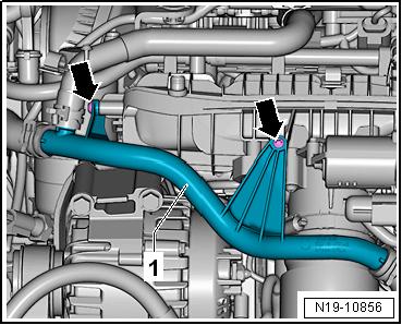
Gr. 27 ; Battery; Battery, Disconnecting and Connecting . – Remove the engine cover. Refer to ⇒ “3.1 Engine Cover, Removing and Installing”, page 38 . – Remove the bolts -arrows-.
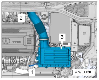
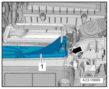
Protected by copyright . Copying for pivate or co merci al pur po s e s , i n p a r t r o r in w ho le, is not permitted unless authorised by Volkswagen AG. Volkswagen AG does notguarantee or accept any liabilit y wi th res pect t o t h e c o r r e c t n e ss o f in format ion in this document. Copyright by Volkswagen AG. – Remove the air filter housing -3-. Refer to ⇒ “3.2 Air Filter Housing, Removing and Installing”, page 294 . m – Remove the left and right bolt -arrow-. – Unclip and remove the lower section -1- of the air duct. – Remove the noise insulation. Refer to ⇒ Body Exterior; Rep. Gr. 66 ; Noise Insulation; Overview - Noise Insulation .