4 minute read
1.2 Engine and Transmission, Separating


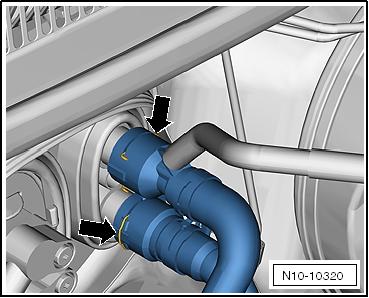
Vehicles without Auxiliary Heater – Lift the clamps -arrows-, remove the coolant hoses from the heater heat exchanger. – Hold the coolant hoses downward and drain the coolant.
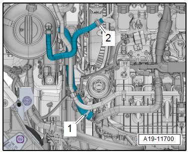
Vehicles with Parking Heater – Loosen the hose clamp -1-, lift the clamps -arrows- and re‐move the coolant hoses.
Continuation for All Vehicles Golf 2015 ➤ , Golf Variant 2015 ➤ Engine Mechanical, Fuel Injection and Ignition - Edition 04.2015
Protected by copyright . Copying for pivate or commerci al pur po s e s , i n p a r t r o r in w ho le, is not permitted unless authorised by Volkswagen AG. Volkswagen AG does notguarantee or accept any liabilit y wi th res pect t o t h e c o r r e c t n e ss o f in format ion in this document. Copyright by Volkswagen AG.
Golf 2015 ➤ , Golf Variant 2015 ➤ Engine Mechanical, Fuel Injection and Ignition - Edition 04.2015
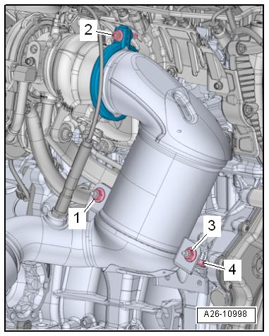
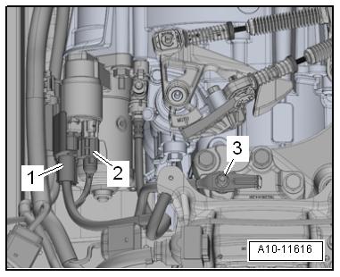
– Remove the connectors -1 and 2- from the holder and discon‐nect them. Then free up the electric wires. – Remove the bolt -2- and the screw-type clamp. – Remove the nuts -1 and 3-.
Note
♦ The installed position is shown in the illustration with the en‐gine removed. ♦ Ignore -4-.
CAUTION
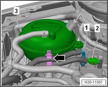
Fuel system is under pressure. Risk of injury from fuel spraying out. – Wear protective eyewear. – Wear safety gloves. – Reduce the pressure: Lay clean cloths around the connec‐tion location and carefully open the connection point.
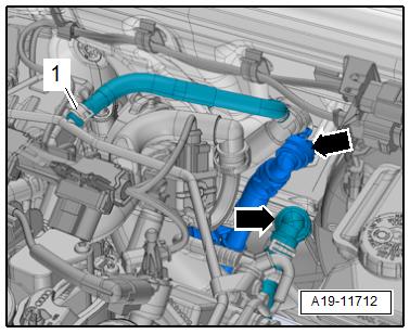
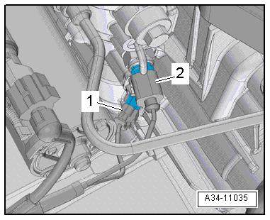
– Disconnect the hose couplings -1 and 2-. Refer to ⇒ Fuel
Supply System; Rep. Gr. 20 ; Connector Couplings; Connec‐tor Couplings, Separating . Loosen the hose clamp from the expansion tank -3-.
Protected by copyright . Copying for pivate or commerci al pur po s e s , i n p a r t r o r in w ho le, is not permitted unless authorised by Volkswagen AG. Volkswagen AG does notguarantee or accept any liabilit y wi th res pect t o t h e c o r r e c t n e ss o f in format ion in this document. Copyright by Volkswagen AG. – Loosen the clamps -1 and 2- and remove the coolant hoses.
Golf 2015 ➤ , Golf Variant 2015 ➤ Engine Mechanical, Fuel Injection and Ignition - Edition 04.2015
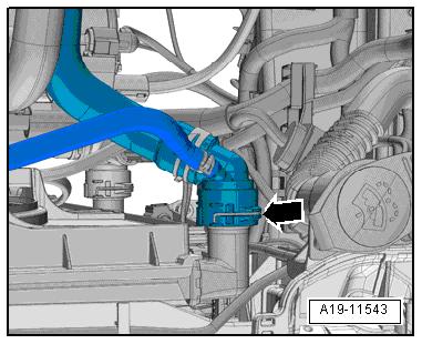
– Lift the clamp -arrow- and remove the upper left coolant hose from the radiator.
Note
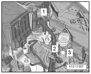
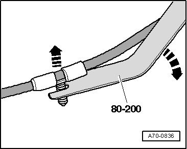
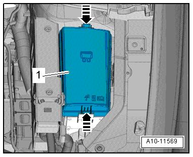
Protected by copyright . Co ying for pivate or commerci al pur po s e s , i n p a r t r o r in w ho le, is not permitted unless authorised by Volkswagen AG. Volkswagen AG does notguarantee or accept any liabilit y wi th res pect t o t h e c o r r e c t n e ss o f in format ion in this document. Copyright by Volkswagen AG. Use the Pry Lever - 80-200- for removing the spiral clips in the following procedure. – Disconnect the connector -1- from the Engine Control Module - J623- . Refer to ⇒ “6.1 Engine Control Module J623 , Removing and Instal‐ling”, page 321 . – Disconnect the connectors -2 and 3- from the bracket. – Free up the wires. p– Release the retainers in direction of -arrows-, and remove the cover -1- from the engine compartment E-box.
Golf 2015 ➤ , Golf Variant 2015 ➤ Engine Mechanical, Fuel Injection and Ignition - Edition 04.2015
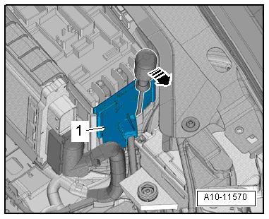
– Open the retainers with a screwdriver in direction of -arrow-, remove the cover -1- for the engine compartment E-box up‐ward.
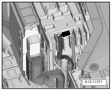
– Remove the nut -arrow-, disconnect and free up the wires.
Vehicles with a Manual Transmission
– Disconnect the connector -2-.
– Push back the B+ terminal protector -1- and disconnect the B + wire from the starter solenoid switch.
– Remove the nut -3- and remove the ground wire.
Note
Protected by copyright . Copying fo pivate or commerci al pur po s e s , i n p a r t r o r in w ho le, is not permitted unless authorised by Volkswagen AG. Volkswagen AG does notguarantee or accept any liabilit y wi th res pect t o t h e c o r r e c t n e ss o f in format ion in this document. Copyright by Volkswagen AG. Depending on the version the ground cable is attached to the starter bolt. – Disconnect the left front connectors from the transmission: 1 - For Transmission Neutral Position Sensor - G701r 2 - For Back-Up Lamp Switch - F4– Remove the gearshift and the selector lever cable from the transmission, remove the cable mounting bracket and move it to the side with the cables. Refer to the ⇒ Controls, Housing; Rep. Gr. 34 ; Selector Mechanism; Selector Mechanism, Re‐moving and Installing repair manual.