5_108.bk Page 194 Thursday, October 4, 2001 11:45 AM
REPAIR INSTRUCTIONS 254
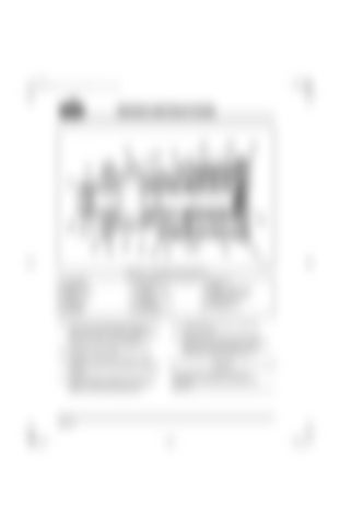
Figure 254 — Raw Water Pump Components 1. Lock Washer 2. Woodruf Key 3. Bearing Housing 4. Oil Seal 5. Slinger O-Ring 6. Water Seal 7. Pump Body 8. Cam/Liner
9. End Cover Screw, 1/4 – 20 x 1/2″ 10. End Cover 11. End Cover Gasket 12. Impeller 13. Seal Retaining Ring 14. Wearplate 15. Lock Washer 16. Screw, 15/16 x 1/2″
24. From drive end of bearing housing, push oil seal (4) into seal bore with lip pointing toward drive end of housing. A light coat of oil may be used to ease installation. 25. Pushing on inner race of bearing, press bearings (17) onto shaft. 26. Pushing on outer race of bearing, install bearing and shaft sub-assembly into bearing housing. 27. Install the bearing retaining ring (19) in the bearing housing, ensuring it is securely seated in the retaining ring groove
Page 194
17. Ball Bearing 18. Shaft 19. Bearing Retaining Ring 20. Adapter Flange Gasket 21. Retaining Washer 22. Drive Gear 23. Hex Nut, 5/8–18″
28. Install slinger O-ring (5) on shaft near bearing housing. 29. Lubricate ceramic seal seat boot with WATER ONLY and press into seal bore of pump body. Exposed ceramic surface should face toward impeller bore.
It is extremely important that the seal components do not become soiled during assembly.


