
2 minute read
REPAIR INSTRUCTIONS


Crankshaft Front Seal Installation
SPECIAL TOOL REQUIRED
After the oil pump has been installed, check the backlash between the auxiliary shaft gear and the oil pump driven gear.
3.Check the auxiliary shaft gear to oil pump driven gear backlash, 0.006–0.016 inch (0.15–0.41 mm), using a thickness gauge between the auxiliary shaft gear and the oil pump driven gear.
Timing Gear Cover Installation
With the crankshaft, camshaft and auxiliary driveshaft in place, install the timing gear cover. Remove the injection pump cover (if installed) from the timing cover to allow access to the injection pump drive gear during injection pump installation.
1.Apply a light coat of Silastic to the timingcover mounting surface.
2.Position the timing cover on the cylinderblock mounting surface.
Some mounting capscrews cannot be installed until the injection pump is installed.
3.Secure the timing cover to the cylinder block using the mounting capscrews. Torque the capscrews to 40 lb-ft (54 N•m) using torque wrench J 24407, or equivalent.
4.Position the front pedestal mount on the timing cover and secure with the mounting hardware. Torque the front support bracket (pedestal mounting) capscrews to 70 lb-ft (95 N•m) using torque wrench J 24407, or equivalent.
r Crankshaft Front Seal Installer J 37715-A
Installation Procedure
Refer to Figure 296.
1.Position the lip-type seal on the seal installer, with the solid portion of the seal outward (toward the tool).
2.Position the tool over hub and into the seal opening.
296
3.Insert the hub capscrew into the hole in the seal installation tool and draw the seal in until the tool bottoms out on the face of the crankshaft.
4.Remove the tool and check the seal to ensure it has been evenly installed.
Page 221
Repair Instructions
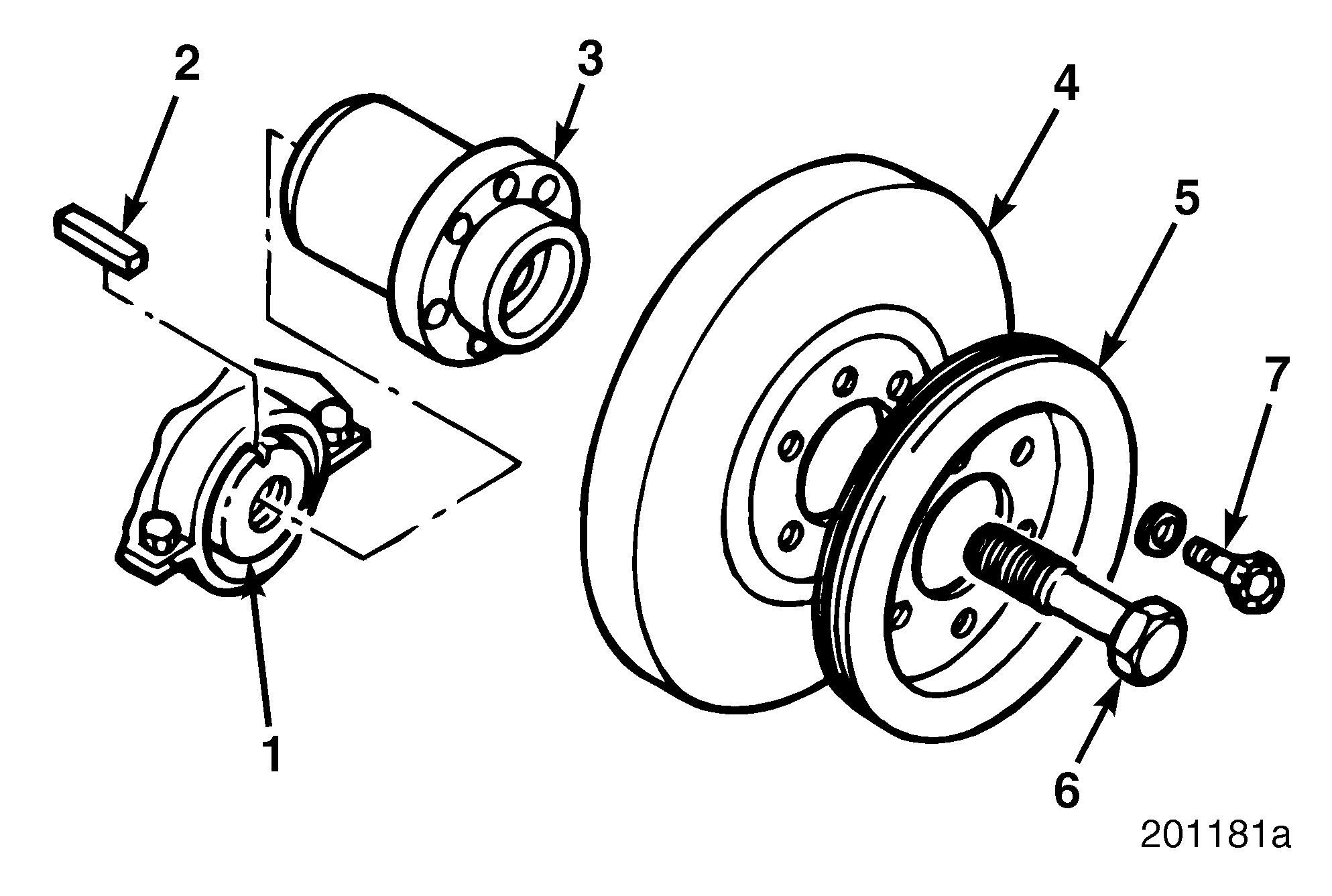
Crankshaft Hub Installation
INSPECTION
Inspect the crankshaft hub for scoring and condition of flange, threaded holes and keyway.
Replace the hub if the seal shows signs of wear. Mack Trucks, Inc. does not recommend the use of a service sleeve to repair the crankshaft hub when there is hub damage. When there is damage to the hub, replace it.
Installation
Refer to Figure 297.
1.Insert hub key in keyway of the crankshaft.
2.Using a suitable grease-type lubricant, coat the working surface of the seal in preparation for crankshaft hub installation.
Teflon-type seals do not require greasing the seal working surface of the crankshaft hub.
3.Heat hub to approximately 250°F (121°C) prior to installation.
4.Using heat-resistant gloves, align keyway in the hub with key in the shaft.
5.In a quick, even motion, push the hub onto the crankshaft.
6.Install hub washer and capscrew. Tighten capscrew to 360 lb-ft (488 N•m) using torque wrench J 23775-01, or equivalent.
Vibration Damper Installation
DESCRIPTION
The vibration damper is mounted to the front of the engine crankshaft hub and secured with six capscrews. The viscous-type vibration damper consists of a flywheel (inertia mass) enclosed in a fluid-tight housing. The vibration damper flywheel and the housing are separated by a thin layer of viscous fluid that is not affected by temperature changes. Any movement of the inertia mass is resisted by the friction of the fluid, which tends to dampen excessive torsional vibrations in the crankshaft.
The vibration damper must be removed whenever the crankshaft front seal, timing gear cover or crankshaft are removed.
When removing or handling the vibration damper, be careful not to damage the housing. Any dents in the damper outer case may render the vibration damper ineffective. An ineffective vibration damper may result in crankshaft cracks. The vibration damper cannot be repaired.


