1 minute read
REPAIR INSTRUCTIONS


Cylinder Head Overhaul
Cylinder Heads
DESCRIPTION
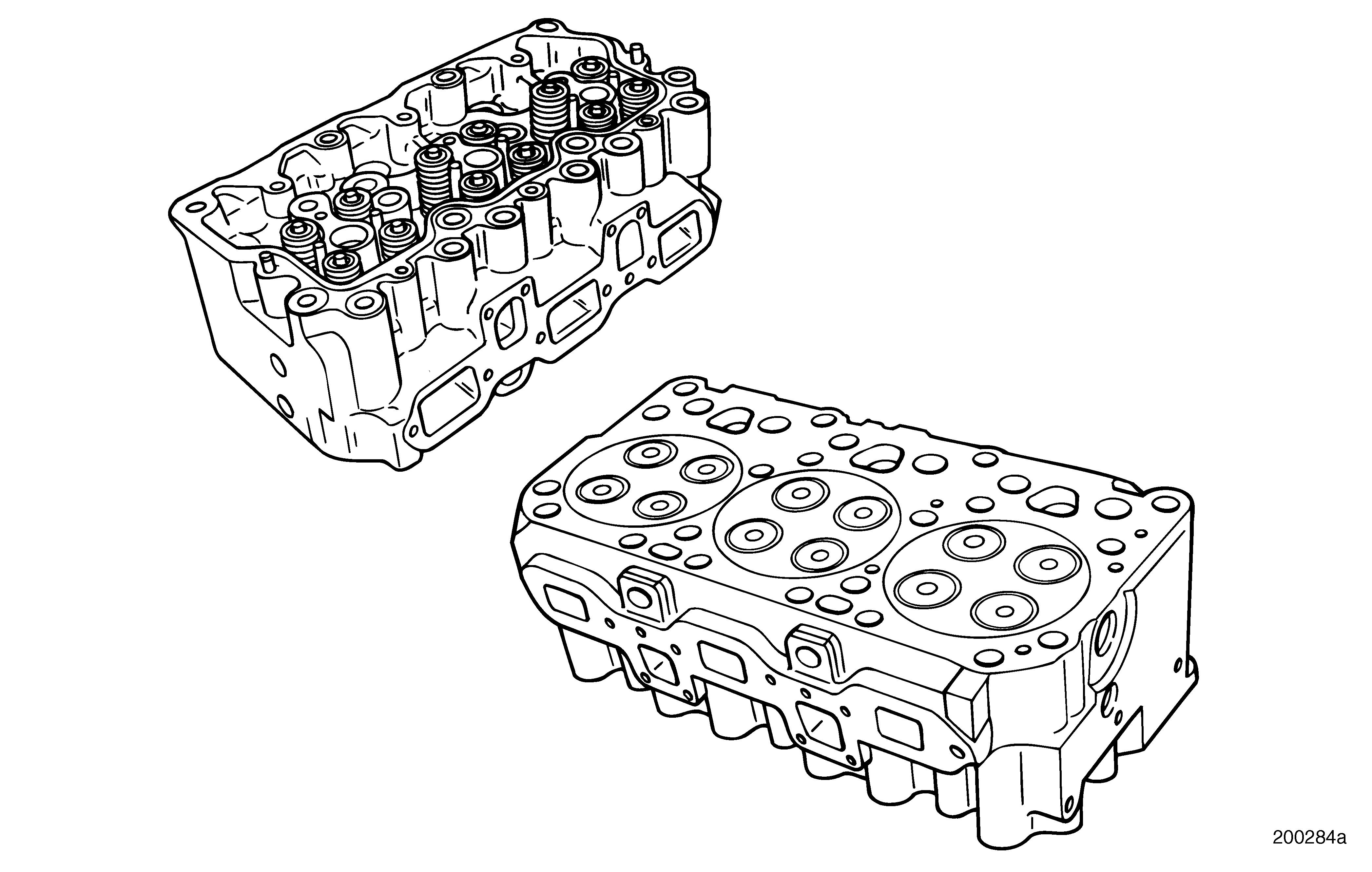
Refer to Figure 202.
The cast iron cylinder head is constructed using a special iron alloy. The head contains cored inlet, exhaust and coolant passages, drilled oil passages, replaceable inlet and exhaust guides and seats, various drilled passages and tapped holes. Each cylinder head covers three cylinders and has two inlet and two exhaust valves per cylinder. Circular grooves correspond with the fire ring bead on cylinder sleeves. This design sets the fire ring over the liner, the lip and into groove of the cylinder head while providing a positive combustion pressure seal. Use a rotary brasswire brush to clean the circular groove.
SPECIAL TOOLS REQUIRED r Valve Spring Keeper Remover J 29294-B r Fire Ring Groove Cutter J 29600-C r M-E7 Cutter Head J 37719 r Depth Gauge J 26948 r Valve Guide Remover J 37482 r Valve Guide Installer J 37809 r Valve Guide Reamer J 37481 r Valve Seat Extractor Kit PT6391 r Collet PT6390-4 r Valve Seat Insert Counterbore HT77136 r Valve Insert Installer Set J 38586 r Driver Handle J 8092 r Prussian Blue r Model MST 50 Universal Spring Tester J 22738-02 r Injection Nozzle Sleeve Extractor J 29880 r Basic Heavy-Duty Dowelout Kit PT6575
Page 157
Repair Instructions
r Dowelout, Extractor (7/16 inch) PT6570-11 r Torque Wrench J 24407 r Slide Hammer J 2619-01 r Valve Yoke Guide Pin Installer J 29296 r Injection Nozzle Sleeve Installer J 29297 r Cylinder Head Core Plug Installer (13/16-inch cup plugs) J 34684 r Cylinder Head Core Plug Installer (1-1/16 inch cup plugs) J 34687 r Valve Seal Installer J 42453 r Valve Stem Seal Remover J 39460
INLET AND EXHAUST VALVE REMOVAL
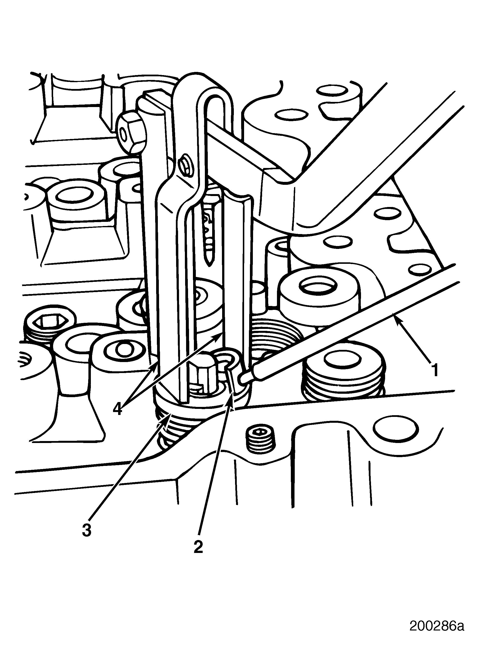
Refer to Figure 203.
1.Attach valve spring keeper remover J 29294-B to cylinder head.
2.Rest tool compression forks (4) on top of upper washer (3) and center forks above valve.
3.Depress tool handle until valve spring is compressed. Remove valve spring washer keys (2) using a magnet (1).
Valve spring keeper remover J 29294-B must be repositioned for each series of valves (two inlet and two exhaust, per cylinder). Drilled and tapped holes are provided for each cylinder.