1 minute read
REPAIR INSTRUCTIONS


Wear protective gloves when handling heated gears.
Refer to Figure 183.
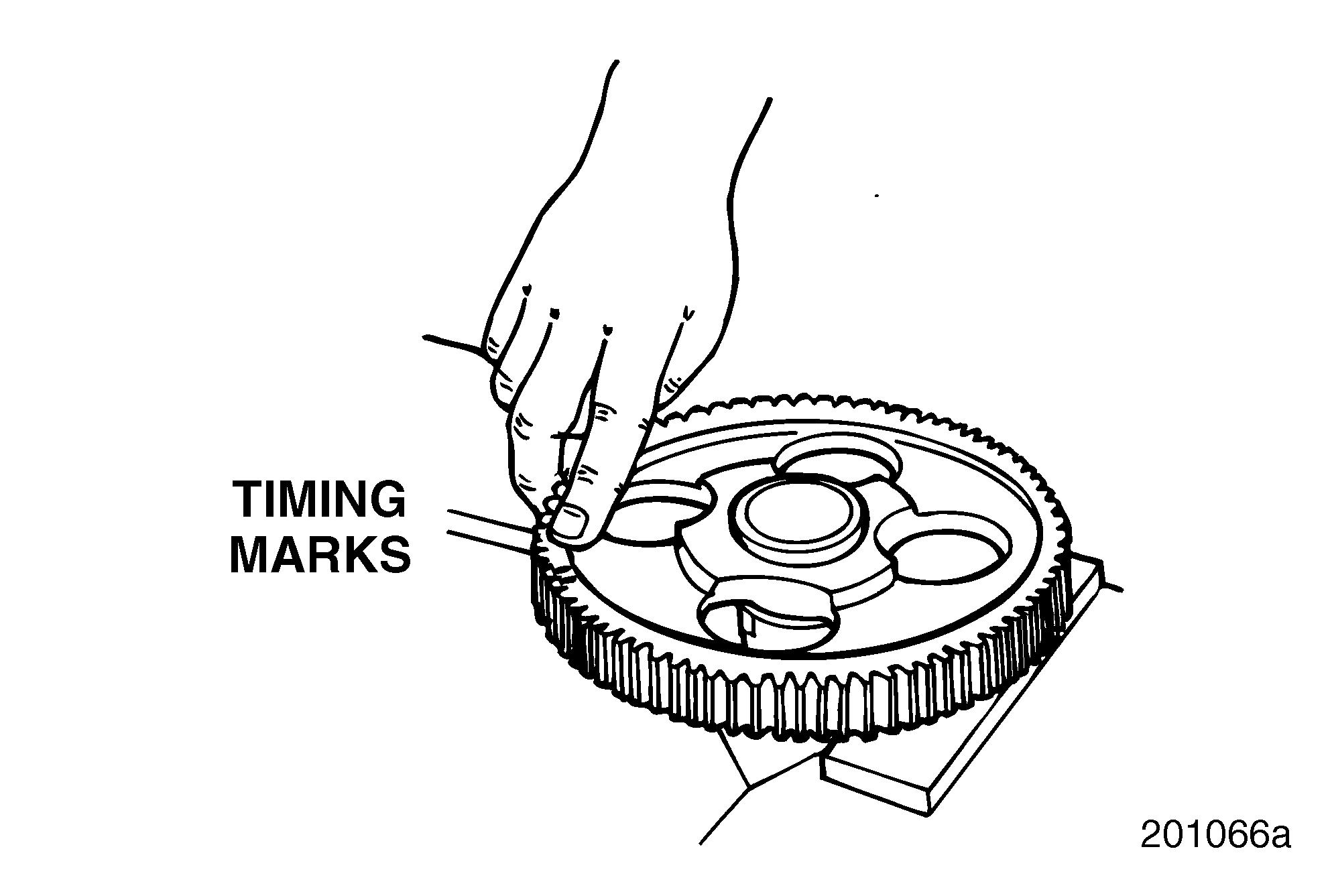
4.Using an oven (not a torch), heat new camshaft gear and new injection pump driving gear to 400°F (205°C). Do not exceed 400°F (205°C) and do not heat for more than one to two hours. Do not exceed two hours. Position camshaft gear with timing marks facing out, and align keyway with key. 183
7.Install injection pump driving gear (5) by applying a quick, even pressure until gear bottoms onto camshaft gear. Make sure camshaft thrust washer holes are accessible through injection pump driving gear.
Camshaft/Injection Pump Driving Gear
Installation Press Method
Refer to Figure 182.
1.Thoroughly clean and degrease camshaft (3) and camshaft drive gear (1) with a suitable contact cleaner that dries rapidly and leaves no residue.
2.Install a new key (4) in camshaft key slot.
3.Place camshaft in a press, making sure camshaft is supported by plates between journal and first lobe.
Approximately 5 tons (4.54 MT) of force is required to press each gear onto the camshaft. When in the press, use suitable plates to support the camshaft between the journal and first lobe. Do not allow camshaft to rest on the floor.
4.Position a new thrust washer (2) on the camshaft.
5.Prepare the gear bore with Locquic™ Primer T, or equivalent.
5.Push downward with a quick, even pressure to install camshaft gear onto camshaft.
The heat-expanded gear bore will begin to transfer heat to the camshaft as soon as the gear bore and camshaft contact each other. This makes it absolutely necessary that the gear be installed in one very rapid motion to the fully seated position. If the gear is allowed to stop on the camshaft part way before fully seating, it will become immovable. If this occurs, do not pressinstall the gear. It should be press removed, allowed to cool, and re-installed using the press method.
6.There should be between 0.003–0.013 inch (0.076–0.330 mm) clearance between rear face of gear and thrust washer when measured with thickness gauge.
6.Apply a bead of Loctite® 609, or equivalent, to the gear bore.
7.Using a clean brush, spread Loctite 609 evenly onto the entire surface of the gear bore.
Refer to Figure 184.
8.Position gear on camshaft with timing marks facing upward and key slot in gear aligned with key in shaft.
Do not attempt to increase clearance between camshaft and gears by sanding gear bores or camshaft.
Page 143


