2 minute read
REPAIR


1. Upper Insert 646B348; Lower Insert 646B343
2. Upper Insert 646B345; Lower Insert 646B343
3. Upper Insert 646B345; Lower Insert 646B343
4. Upper Insert 646B349; Lower Insert 646B344
5.Apply a light coat of clean engine oil on the insert surfaces and on the crankshaft main bearing journals.
Due to the considerable weight of the crankshaft, extreme care must be observed during installation. No nicks, scratches, burrs, or any other kinds of distress are acceptable on the main bearing and/or crankshaft journals and fillets.
5. Upper Insert 646B345; Lower Insert 646B343
6. Upper Insert 646B345; Lower Insert 646B343
7. Upper Insert 646B350; Lower Insert 646B344
6.Using a suitable lifting device, position the crankshaft in the cylinder block.
Repair Instructions
Main Bearing Cap Installation
SPECIAL TOOL REQUIRED r Magnetic Base Indicator Tool J 7872
Installation Procedure
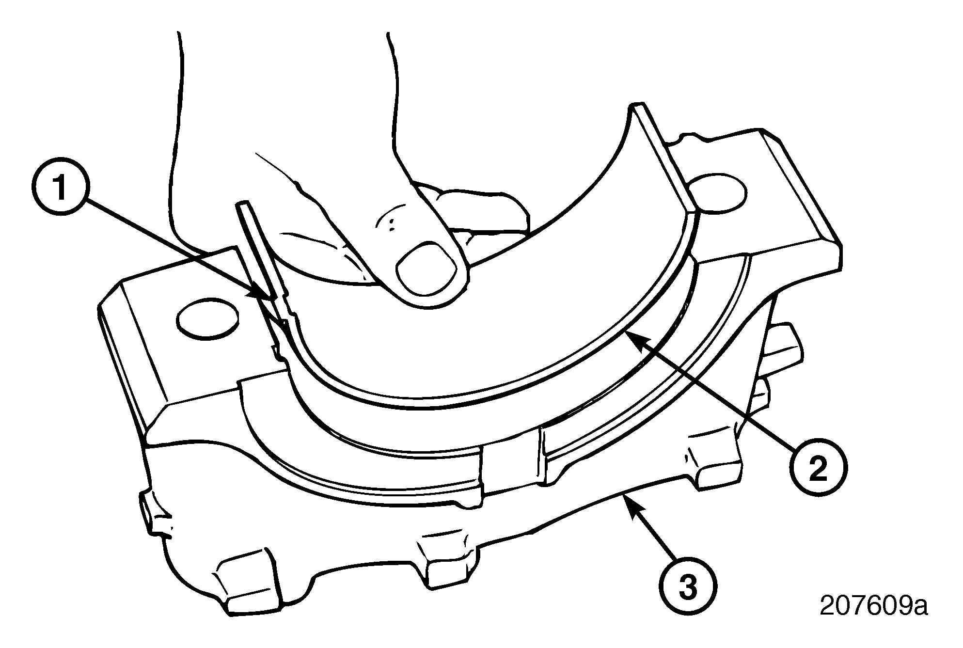
1.Clean the bore in the bearing cap and back of the lower bearing insert.
2.Install the bearing insert in the bearing cap bore (Figure 269). The insert must be installed dry.
The lower bearing inserts do not have a hole or a groove. They are stamped with the word “LOWER.”
3.Lubricate the threads of the bearing capscrews with clean engine oil and place capscrews in the cap holes.
4.Position the No. 1 bearing cap over the No. 1 crankshaft journal and start the screws in the threaded holes in the cylinder block.
5.Using a plastic-faced mallet, tap the bearing cap down until it contacts the machined mounting surface.
6.Tighten the screws until they contact the bearing cap. At this time, tighten them only finger-tight.
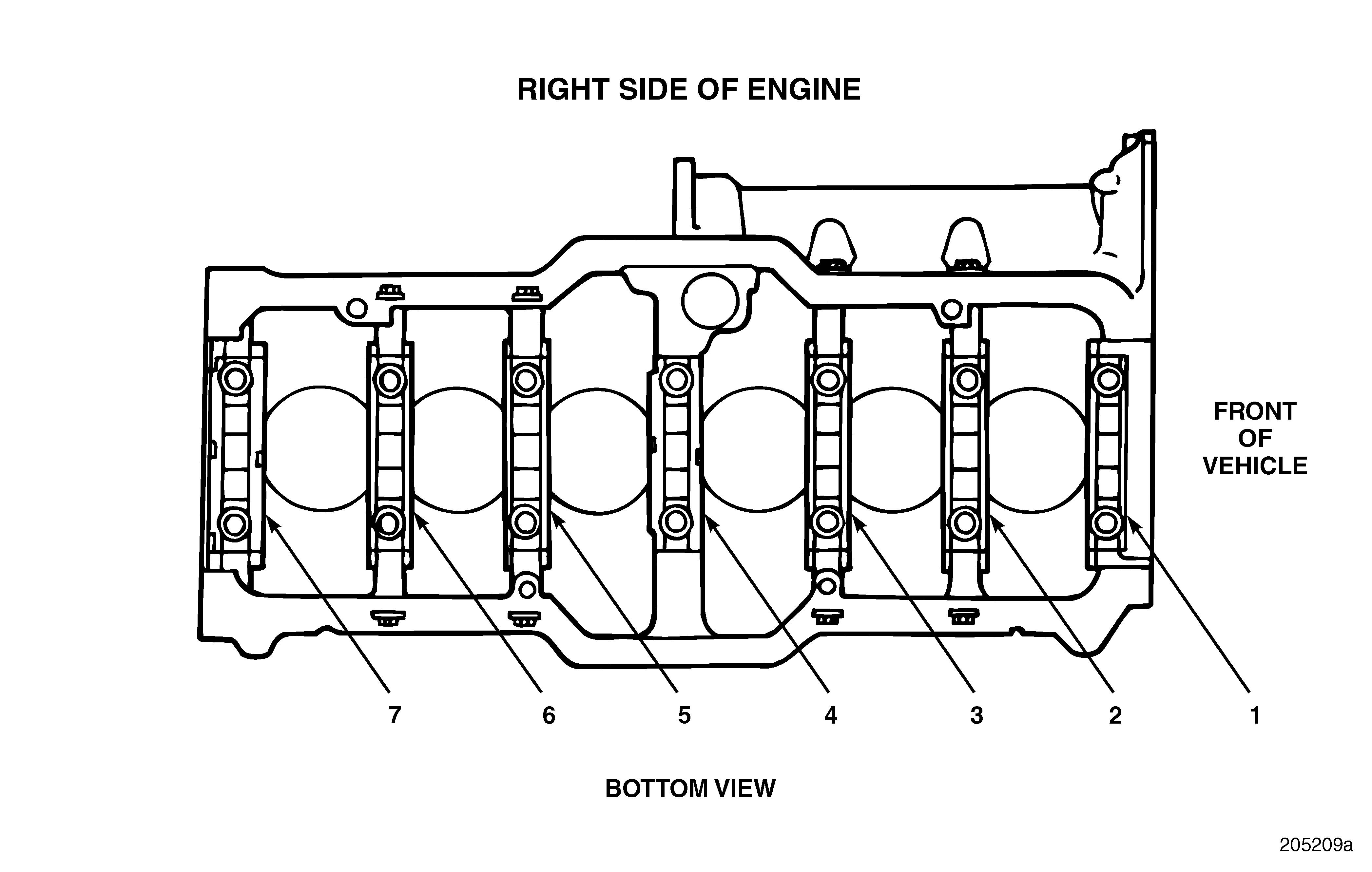
7.Repeat the above steps for the bearing cap Nos. 2, 3, 5, 6 and 7. The center bearing cap, No. 4, is installed later.
8.Tighten the bearing cap capscrews to specification, 200–220 lb-ft (271–298 N•m), using torque wrench J 24407, or equivalent.
Do not mix the caps or inserts. The caps are numbered from 1 through 7, front to rear.
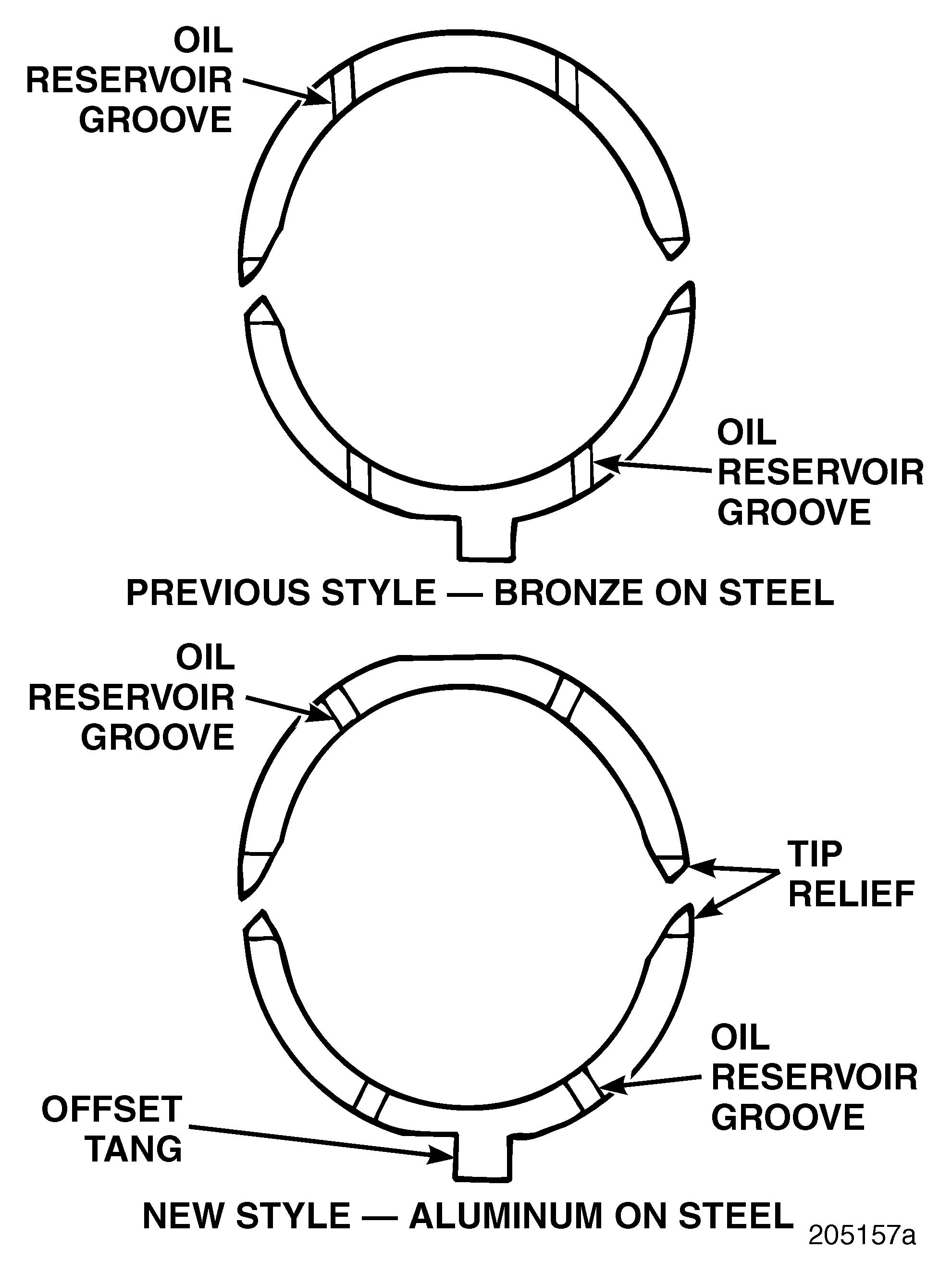
9.Place the upper thrust washer sections in position in the cylinder block at the center bearing, No. 4, location as shown in Figure 271. The steel side of the thrust washer goes toward the block, the copper or aluminum-faced side goes toward the crankshaft (this applies to upper and lower thrust washer sections). Oil reservoir grooves are cut into the aluminum-faced side, as well as tip-face reliefs.
Use standard thickness thrust washers initially.
Thrust washers are steel-backed with an aluminum facing material on the side installed against the crankshaft. The obvious color difference of the previously used bronze/steel washers is no longer present making it difficult to determine which side of the washer is meant to be installed against the crankshaft. Care should be taken when installing these aluminum-faced thrust washers as the steel side is nearly the same color as the aluminum surface. Locate the oil reservoir grooves and the tip reliefs cut into the aluminum, and install those sides against the crankshaft.
To prevent damage, ensure the thrust washers are installed in the correct position when assembling an engine. Failure to install the thrust washer properly will result in rapid wear of the area where the crankshaft contacts the thrust washer.
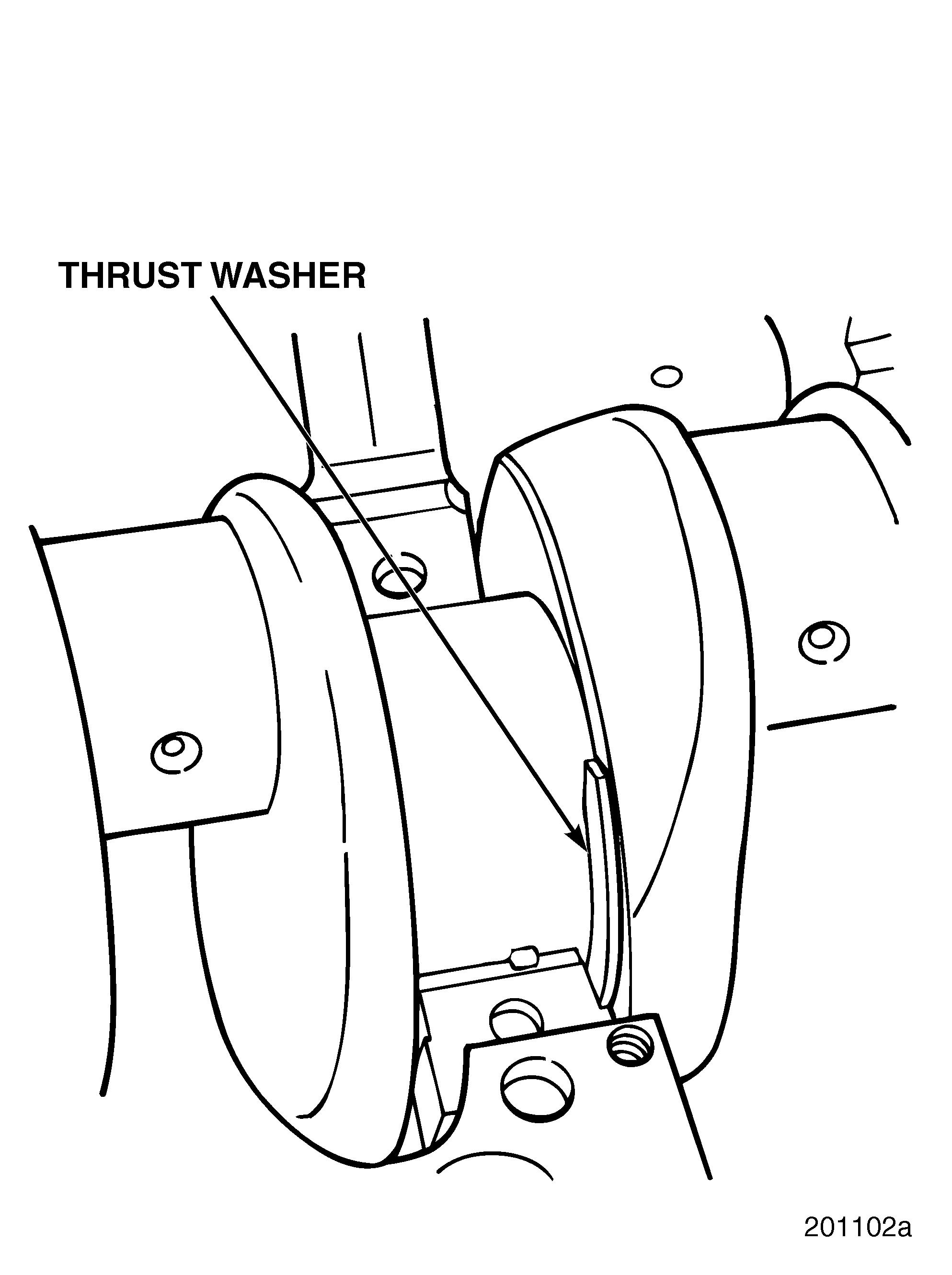
10.Position the lower thrust washer sections on the center bearing cap (aluminum-faced side toward crankshaft) and install the cap (Figure 272). Torque the capscrews to specification, using torque wrench J 24407, or equivalent.