2 minute read
REPAIR INSTRUCTIONS


New standard bearing inserts (manufacturing date of 10-00 or later) are 0.0006 inch larger than the old standard bearings. These new bearings reduce the bearing running clearance to provide a slight increase in engine oil pressure. This reduction of bearing running clearance makes it absolutely essential that Plastigage check be performed to verify that a minimum running clearance of 0.0018 inch (0.045 mm) is maintained.
8.Reposition the cap on the journal. Lubricate the capscrews with clean engine oil of the proper specification. Lubricate and install the bearing cap buttress capscrews as required, finger-tight. Install the bearing cap capscrews and tighten to the specified torque value, using torque wrench J 24407, or equivalent.
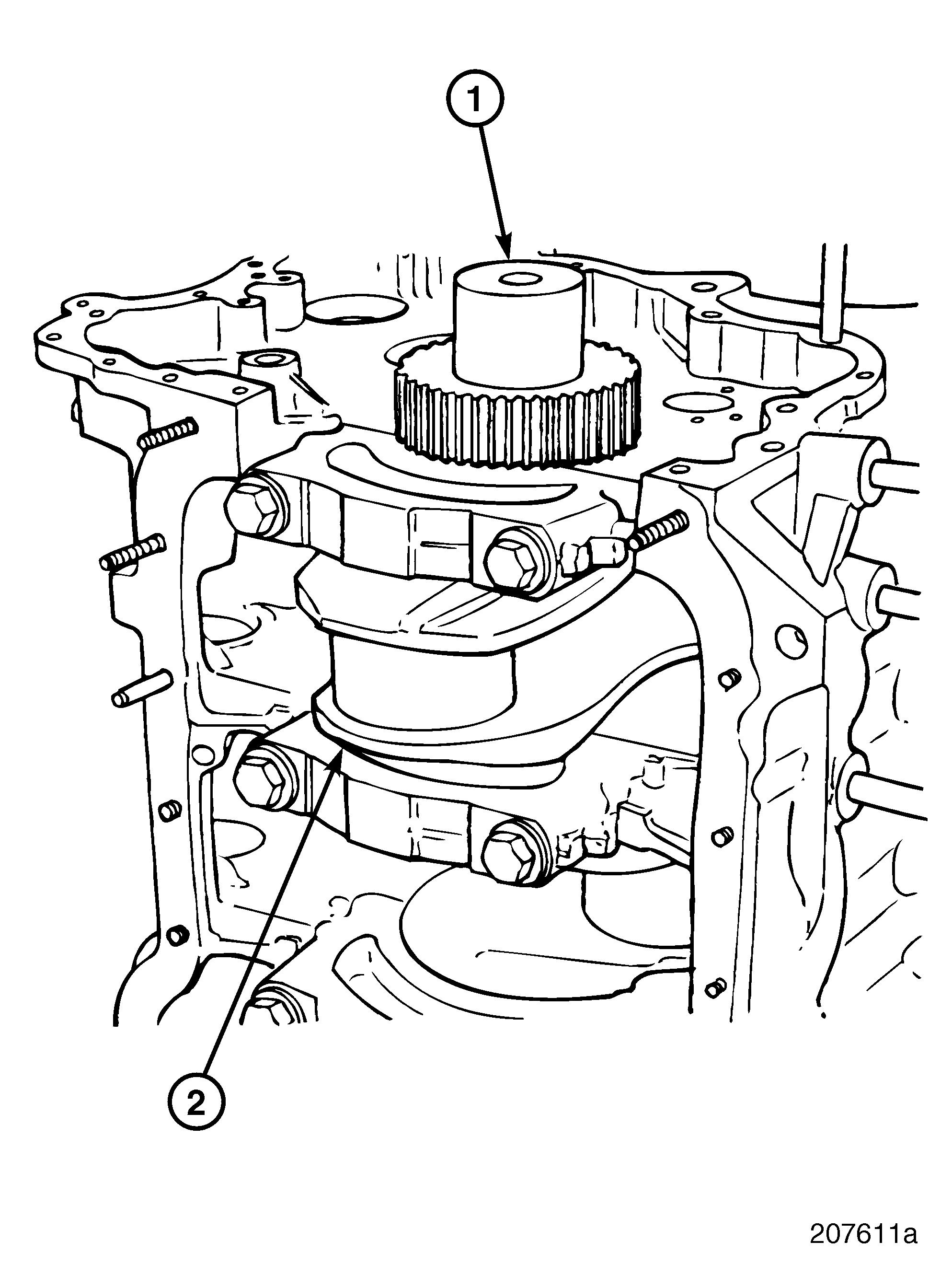
Refer to Figure 274.
There are two buttress capscrew dimensions: r LH side 2, 3, 5, 6 and RH side 5 and 6 (6 total) are 80 mm long (1). r RH side FRT 2 and 3 (2 total) are 110 mm long (2).
274
Repair Instructions
9.After obtaining the proper main bearing clearance at all seven journal locations, check the torque of the main bearing capscrews, using torque wrench J 24407, or equivalent.
10.Tighten the buttress capscrews to the specified torque, using torque wrench J 24407, or equivalent.
Piston and Connecting Rod Installation
SPECIAL TOOLS REQUIRED r Piston Ring Compressor J 23442 or Piston Ring Compressor PT7070-A r Torque Angle Gauge BT91104
INSTALLATION PROCEDURE
1.Rotate the crankshaft so that the journals for the No. 1 and No. 6 cylinders are at bottom dead center (BDC) (Figure 275).
2.Place the piston marked No. 1 on a clean, flat surface. Rest the piston and rod assembly on the piston crown with the rod upward.
3.Apply a light coat of clean engine oil to the piston and rings.
4.Apply a light coat of clean engine oil to the inside surface of the piston ring compressor, J 23442, PT7070-A, or equivalent.
5.Install the ring compressor by slipping it over the rod and down over the piston skirt. Continue to slide the tool downward, carefully guiding the rings into the ring grooves until the tool contacts the surface on which the piston crown is resting.
6.Position the upper bearing insert into the connecting rod. Align the tab in the bearing insert with the notch in the rod. Be sure that the hole in the bearing aligns with the oil passage in the rod.
The hole in the upper connecting rod bearing must be aligned with the oil passage in the connecting rod. Otherwise, damage to the bearing, rod and crankshaft journal will result.
7.Apply a light coat of clean engine oil to the bearing surface.
8.Apply a light coat of clean engine oil to the inside surface of the No. 1 cylinder sleeve.
9.With the ring compressor (2) in place, position the piston and rod assembly (1) into the No. 1 cylinder as shown in Figure 276 until the compressor contacts the top of the sleeve. The arrow and word FRONT on both the piston crown and the connecting rod must be facing the front of the engine.
Page 207